GD&T Basics: Symbols, Importance & How It Works?
Ever wondered how makers make complex parts fit together perfectly? It’s all about a special language used in the making world.
Geometric Dimensioning and Tolerancing (GD&T) helps share important making info. It’s key for CNC machines that need parts to fit just right.
It’s a clear way to set part sizes and how much they can vary. Knowing GD&T basics is a must for makers, engineers, and quality checkers.
Key Takeaways
- Understanding the importance of GD&T in manufacturing.
- Learning the basics of GD&T and its symbolic language.
- Discovering how GD&T works in CNC machining processes.
- Recognizing the role of GD&T in ensuring part accuracy.
- Appreciating the significance of GD&T in quality control.
Introduction to GD&T
Geometric Dimensioning and Tolerancing (GD&T) is key in today’s manufacturing. It acts as a language for parts and assemblies’ design intent and specs.
What Is GD&T?
GD&T uses symbols and standards to share manufacturing info. It accurately describes parts’ size, shape, and position. This system is vital for parts to fit and work right.
Why GD&T Is Used
GD&T ensures parts are made as designed. It offers a clear language, cutting down on errors and misunderstandings. This boosts the quality of the final product.
“The use of GD&T has become essential in modern manufacturing, as it provides a standardized way to communicate complex design information.”
History and Standards (ASME & ISO)
GD&T started in 1938 and has grown into a detailed system. In the U.S., the ASME Y14.5-2018 standard guides it. Globally, the ISO 1101-2017 standard is followed.
| Standard | Description | Region |
|---|---|---|
| ASME Y14.5-2018 | Standard for GD&T in the United States | USA |
| ISO 1101-2017 | International standard for GD&T | Global |
Knowing these standards is essential for GD&T work. They help in correctly applying GD&T principles.
Importance of GD&T
GD&T is key for making products fit well, saving money, and boosting quality. It sets the rules for how parts fit together. This way, parts work right and meet the needed standards.
Ensuring Functional Fit
GD&T makes sure parts fit right together. It lets makers create parts that can swap out easily. Experts say,
“GD&T provides a common language for engineers and manufacturers, ensuring that parts are made to the required specifications.”
Knowing the GD&T symbols chart and meanings is vital. It helps share tolerances and sizes clearly.

Improving Communication in Engineering
GD&T makes talking between engineers, makers, and inspectors clearer. It uses a standard way to talk about tolerances. This cuts down on mistakes and makes making things faster.
With GD&T, everyone knows what to expect. This makes making parts easier and safer. Designers can trust their work will meet standards.
Reducing Manufacturing Costs
Using GD&T can cut down on making costs. It helps avoid waste and extra work. By knowing what’s okay, makers save money.
GD&T also helps makers use the best tolerances. This saves money by not needing too tight fits. Knowing GD&T symbols helps makers work smarter and cheaper.
Enhancing Part Interchangeability
GD&T makes parts easier to swap out. This is key in today’s making world. Parts come from different places and must fit together.
GD&T sets the rules for sizes and fits. This makes sure parts work together well. It’s important for making complex things work right.
Core Elements of GD&T
GD&T is built on key elements like tolerance zones and feature control frames. These parts work together to make sure parts are made exactly as needed.
Tolerance Zone
A tolerance zone shows how much a part can vary from its exact shape. It sets limits for how much a feature can change. For example, it might cover the size of a hole or the flatness of a surface.
Tolerance zones are critical because they affect how well parts work together. They make sure parts fit as planned.
Feature Control Frame
The feature control frame is a key part of GD&T. It lets engineers set tolerances and use datums. It’s like a box that holds the tolerance info for a feature.
Inside the feature control frame, you’ll find symbols, tolerance values, and modifiers. For instance, it might use the gdt flatness symbol for a surface’s flatness.
| Geometric Characteristic | Tolerance Value | Modifiers |
|---|---|---|
| Flatness | 0.01 | MMC |
| Straightness | 0.005 | LMC |
Datums and Datum Reference Frames
Datums are key points, axes, or planes for measuring and tolerancing. A datum reference frame is a system that sets a part’s location and orientation.
Datums are essential because they help everyone talk about part geometry. They make sure parts are made and checked right.
Material Condition Modifiers
Material condition modifiers tell us about a feature’s material condition, like MMC or LMC. These modifiers change the tolerance zone. They’re key for parts to fit right.
Knowing and using these GD&T elements helps engineers and makers make parts exactly right. This reduces mistakes and boosts product quality.
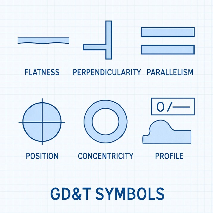
GD&T Symbol Categories
To fully understand GD&T, it’s key to know its symbol categories. GD&T symbols cover form, orientation, location, and profile tolerances. Each category helps in reading engineering drawings and making sure parts meet specifications.
Form Tolerances
Form tolerances show how much a feature can vary in shape. They’re important for parts to fit and work right. Symbols for form tolerances include straightness, flatness, circularity, and cylindricity.
- Straightness: Specifies the allowable deviation from a perfect straight line.
- Flatness: Defines the allowable deviation from a perfect plane.
- Circularity: Specifies the allowable deviation from a perfect circle.
- Cylindricity: Defines the allowable deviation from a perfect cylinder.
Orientation Tolerances
Orientation tolerances control how features align with a datum. They make sure parts are correctly aligned. Symbols for these include parallelism, perpendicularity, and angularity.
“Orientation tolerances are critical in ensuring that parts fit together correctly and function as intended.”
- Parallelism: Specifies the allowable deviation from parallel to a datum.
- Perpendicularity: Defines the allowable deviation from perpendicular to a datum.
- Angularity: Specifies the allowable deviation from a specified angle relative to a datum.
Location Tolerances
Location tolerances show how much a feature can vary in position. They’re key for parts to be in the right place. Symbols for these include position, concentricity, and symmetry.
| Symbol | Description | Usage |
|---|---|---|
| Position | Specifies the allowable deviation from a specified location. | Used to control the location of features such as holes and slots. |
| Concentricity | Defines the allowable deviation from concentricity. | Used to control the coaxiality of features. |
| Symmetry | Specifies the allowable deviation from symmetry. | Used to control the symmetry of features. |
Profile Tolerances
Profile tolerances show how much a feature’s shape can vary. They’re used for complex shapes. Symbols for these include profile of a line and profile of a surface.
Profile tolerances are key for making sure complex features are made right.
Common GD&T Symbols and Definitions
GD&T symbols in engineering drawings help everyone talk clearly. They make sure everyone knows what the part should look like. This is key for designers, makers, and inspectors to work well together.
Position
The position symbol shows where a feature or group of features should be. It’s very important for parts to fit right together.
Flatness
Flatness means a surface is in two parallel planes. The flatness GD&T symbol tells us where the surface should be. This is very important for parts that need to be flat for working or fitting together.
Straightness
Straightness means a line or axis is straight. The straightness symbol helps keep features straight. This is key for parts like shafts or holes that must be straight to work right.
Circularity
Circularity, or roundness, is how close a feature is to a perfect circle. The circularity symbol sets the limits for how round a feature should be. This is very important for parts that spin, like gears, because roundness affects how well they work and how long they last.
| GD&T Symbol | Description | Application |
|---|---|---|
| Position | Defines the location of a feature relative to a datum. | Used for features that need to be positioned accurately relative to other features or datums. |
| Flatness | Specifies the tolerance zone for a surface to be considered flat. | Applied to surfaces that require a high degree of flatness for functional or assembly purposes. |
| Straightness | Controls the deviation of a feature from a straight line. | Used for features like shafts or holes that need to be straight. |
| Circularity | Specifies the tolerance for a feature to be considered round. | Crucial for rotating parts where circularity affects performance and wear. |
Knowing about GD&T symbols is key for clear talk and making parts right. By setting the right geometric tolerances, engineers make sure parts fit, work, and can be swapped out easily.
Understanding Datums in GD&T
Datums are key to using GD&T well. They help set up tolerances and measurements. Datums are points or surfaces that guide how parts are measured and controlled.
What Are Datums?
Datums are exact points, axes, or planes for measuring and tolerancing. They’re not physical on a part but come from its features. The datum system makes part geometry clear and useful.
The ASME Y14.5-2009 standard says datums are “a theoretically exact point, axis, line, or plane used as a reference for dimensional tolerancing.”
Datum Features
Datum features are real parts used to set a datum. These can be surfaces, edges, or shapes. Picking the right datum features is important for part measurement and tolerancing.
Datum features should be chosen based on their functional importance and their ability to be accurately measured. For example, a surface that mates with another part is often a good candidate for a datum feature.

Primary, Secondary & Tertiary Datums
Datums are sorted into primary, secondary, and tertiary based on their order. This order is key for part measurement.
- Primary Datum: The first datum specified, which provides the initial reference for measurement.
- Secondary Datum: The second datum, which further refines the orientation of the part.
- Tertiary Datum: The third datum, which completes the datum reference frame.
| Datum Order | Description |
|---|---|
| Primary | Initial reference for measurement |
| Secondary | Refines the orientation of the part |
| Tertiary | Completes the datum reference frame |
How Datums Guide Measurement
Datums help guide measurement by providing a clear reference frame. This ensures parts are measured and checked the same way. It reduces errors and misinterpretations.
“The datum system is a critical component of GD&T, as it enables the precise specification and measurement of part geometry.”
By understanding and using datums right, engineers and manufacturers can make better parts. This leads to products that work better and are more reliable.
How GD&T Works in Practice
In the real world, GD&T is used on engineering drawings. It sets tolerances and datums to make sure parts fit right. This is key for making parts precise and functional.
Applying GD&T to Engineering Drawings
GD&T is applied to engineering drawings to share design intent and specs. It uses symbols and annotations. This helps manufacturing and inspection teams know what’s needed.
Example: A mechanical drawing of a shaft might include a position tolerance. This shows the acceptable deviation from the ideal location.
Determining Functional Requirements
Before using GD&T, figuring out the part’s function is key. You need to find out which features are most important. These features affect how well the part works and fits with others.
- Identify critical features that affect function and fit.
- Analyze the part’s interaction with other components.
- Establish the required tolerances based on the functional requirements.
Establishing the Datum System
A datum system is a reference for measuring and inspecting parts. It’s set up by picking primary, secondary, and tertiary datums. These datums help orient and locate the part.
| Datum | Description |
|---|---|
| Primary Datum | The primary reference point or surface. |
| Secondary Datum | The secondary reference point or surface, used in conjunction with the primary datum. |
| Tertiary Datum | The tertiary reference point or surface, used to further constrain the part. |
Measuring and Inspecting GD&T Tolerances
After setting GD&T tolerances, measuring and inspecting parts is vital. This ensures they meet the standards. Various tools and techniques are used, like Coordinate Measuring Machines (CMMs) and optical comparators.
Inspection Techniques: CMMs, optical comparators, and other tools are used. They check if parts meet the GD&T tolerances.
Benefits of Implementing GD&T
Using Geometric Dimensioning and Tolerancing (GD&T) in engineering designs boosts the quality and function of products. It helps ensure parts are made to exact standards. This is thanks to a detailed gdt symbols chart.
Enhanced Fit and Functionality
GD&T lets designers set clear functional needs for parts. This leads to better fit and function. It also cuts down on assembly errors.
Reduced Ambiguity in Design
GD&T removes confusion in engineering drawings with a standard language for tolerances. This clear language cuts down on misunderstandings. It makes sure parts are made as planned.
Improved Manufacturing Flexibility
GD&T makes production processes clearer and more flexible. It sets a clear datum system and tolerance specs. This makes production more efficient and cost-effective. It also helps adapt to changing needs.
Using GD&T leads to parts of higher quality. It reduces confusion and boosts production flexibility. This results in better products and lower costs.
FAQ
What does GD&T stand for?
GD&T stands for Geometric Dimensioning and Tolerancing. It’s a system for defining and communicating part dimensions and geometry tolerances.
What is the purpose of using GD&T symbols?
GD&T symbols help convey a part’s design intent and specifications. They ensure the part is made and checked correctly. This meets the needed functional and assembly standards.
What is the difference between ASME and ISO GD&T standards?
ASME and ISO are two standards for GD&T. They share similarities but have differences in definitions and rules. ASME is mainly used in the U.S., while ISO is international.
What is a datum in GD&T?
A datum is a reference point, axis, or plane for measuring a part’s dimensions and geometry. It helps establish a coordinate system for accurate measurements.
What is the flatness GD&T symbol?
The flatness GD&T symbol shows the tolerance zone for a surface to be considered flat. It’s represented by a parallelogram symbol.
How do GD&T symbols improve communication in engineering?
GD&T symbols offer a standardized way to communicate part design and specifications. This reduces confusion and ensures everyone is clear on the design intent.
What are the benefits of implementing GD&T?
Using GD&T improves part fit and function. It reduces confusion and enhances manufacturing flexibility. This leads to cost savings and better product quality.
What is the role of material condition modifiers in GD&T?
Material condition modifiers specify when a tolerance applies. They can be for maximum material condition (MMC) or least material condition (LMC).
How are GD&T tolerances measured and inspected?
Tolerances are measured and inspected with tools like coordinate measuring machines (CMMs) and optical comparators. These ensure parts meet the specified tolerances.