Machining Titanium Grade 5 (Ti-6Al-4V): Cutting Speeds, Tool Wear & High-Pressure Cooling Guide

Titanium Grade 5 (Ti-6Al-4V, UNS R56400, Werkstoff 3.7165) represents the workhorse alloy of aerospace, medical implantology, and high-performance motorsport engineering. Possessing a dual-phase alpha-beta (α+β) microstructure stabilized by 6% aluminum and 4% vanadium, it delivers an exceptional strength-to-weight ratio (yield strength exceeding 880 MPa at a density of 4.43 g/cm³), outstanding fracture toughness, and superior corrosion resistance in saline and physiological environments.
However, from the perspective of subtractive CNC manufacturing, Ti-6Al-4V is classified as an extraordinarily difficult-to-cut material. Its mechanical behavior during metal cutting diverges fundamentally from structural carbon steels or aerospace-grade aluminum alloys, governed by three thermodynamic and metallurgical mechanisms:
First, Ti-6Al-4V exhibits an extremely low thermal conductivity of approximately 6.7 W/(m·K) at room temperature, compared to roughly 50 W/(m·K) for AISI 4140 alloy steel and over 150 W/(m·K) for 7075-T6 aluminum. In standard metal cutting, approximately 75% to 80% of the thermal energy generated in the primary and secondary shear zones is carried away by the ejected chips. In titanium, this thermal dissipation mechanism collapses: over 80% of the cutting heat remains trapped at the immediate tool-chip interface and cutting edge. Localized contact zone temperatures routinely exceed 800°C to 1,000°C, causing rapid thermal breakdown of cutting tool binders and coatings.
Second, titanium displays an erratic chip formation mechanic known as adiabatic shear banding. Instead of forming continuous, uniform ribbon chips, Ti-6Al-4V generates saw-toothed, serrated (segmented) chips. As the cutting edge engages the material, localized plastic deformation generates intense heat faster than it can dissipate. This triggers catastrophic thermal softening along narrow shear bands, alternating rapidly with brittle fracture. This cycle occurs at frequencies between 10 kHz and 50 kHz, subjecting the cutting edge to continuous, high-frequency mechanical shock and thermal cycling that accelerates micro-chipping and notch wear at the depth-of-cut line.
Third, Ti-6Al-4V possesses a low modulus of elasticity (approximately 110 to 114 GPa, roughly half that of structural steel) combined with high chemical reactivity at elevated temperatures. Under cutting tool pressures, the workpiece deflects elastically away from the tool and snaps back against the tool clearance flank immediately behind the cutting edge. This springback generates intense friction, rapid flank wear, and severe structural chatter.
Simultaneously, above 500°C, titanium becomes chemically aggressive, readily welding itself to tungsten carbide substrates via diffusion, forming built-up edge (BUE) deposits that pull out tool substrate grains upon separation.
Overcoming these physics-based failure modes requires strict discipline in parameter selection, advanced cutting tool substrates, high-rigidity machining centers, and optimized high-pressure fluid delivery. Hardware engineering teams looking for proven aerospace-grade component execution can partner with Celerity Precision through our custom titanium CNC machining services.
Table of Contents
Speeds, Feeds & Machining Parameters
Successful titanium machining relies on a counterintuitive principle: cut at low surface speeds (to keep the thermal generation rate below the tool substrate degradation threshold), maintain aggressive, positive chip loads (to ensure the cutting edge shears beneath the work-hardened layer formed by the previous pass), and maximize coolant delivery directly to the shear zone.
Dwelling or rubbing with an inadequate feed per tooth rapidly work-hardens the surface and destroys the tool cutting edge within seconds.
The following industrial parameter matrix outlines validated starting baselines for conventional milling, slotting, face milling, and turning across annealed Ti-6Al-4V (Rockwell Hardness 32–36 HRC):
| Machining Operation | Tooling & Coating | Speed (SFM) |
Speed (m/min) |
Chip Load / Feed (FPT / IPR) |
Radial (Ae) | Axial (Ap) |
|---|---|---|---|---|---|---|
| End Milling - Roughing | Sub-micron Carbide (AlCrN) | 130 – 210 | 40 – 65 | 0.05 – 0.10 mm/tooth | 0.30 – 0.50 × D | 0.50 – 1.00 × D |
| End Milling - Finishing | Sub-micron Carbide (TiCN/AlCrN) | 180 – 260 | 55 – 80 | 0.025 – 0.06 mm/tooth | 0.05 – 0.10 × D | 1.00 – 1.50 × D |
| Slotting (Full Width) | Sub-micron Carbide (AlCrN) | 100 – 150 | 30 – 45 | 0.035 – 0.07 mm/tooth | 1.00 × D (Full) | 0.25 – 0.50 × D |
| Face Milling | Indexable Inserts (AlCrN/TiAlN) | 140 – 220 | 42 – 68 | 0.10 – 0.18 mm/tooth | 0.60 – 0.75 × D | 1.50 – 3.00 mm |
| OD/ID Turning - Rough | ISO Carbide (CNMG/WNMG) | 150 – 240 | 45 – 75 | 0.15 – 0.30 mm/rev | N/A | 1.50 – 3.50 mm |
| OD/ID Turning - Finish | ISO Carbide (CCMT/VBMT) | 220 – 320 | 65 – 100 | 0.06 – 0.12 mm/rev | N/A | 0.25 – 0.75 mm |
| Trochoidal Milling HEM Strategy | 5-Flute Solid Carbide | 280 – 450 | 85 – 140 | 0.08 – 0.16 mm/tooth | 0.05 – 0.10 × D | 2.00 – 3.00 × D |
Dynamic / Trochoidal Milling (High-Efficiency Milling – HEM)
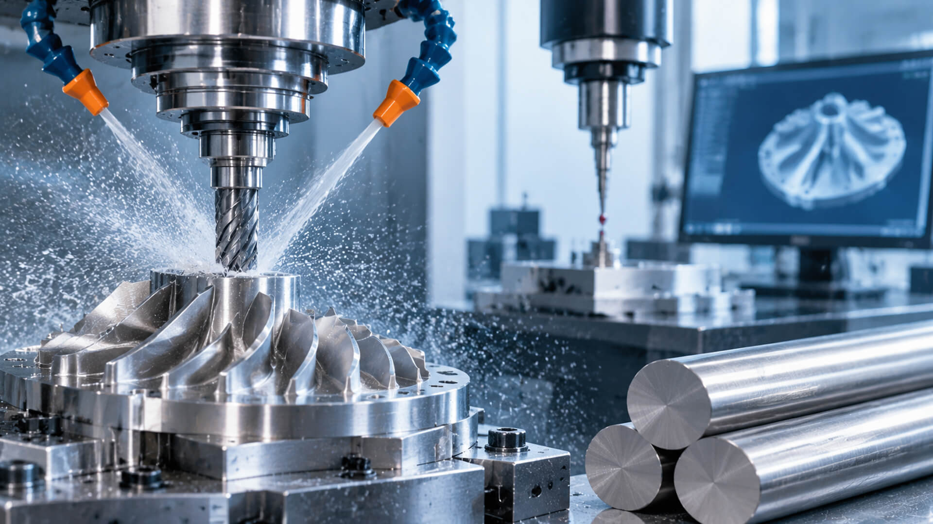
In modern CNC aerospace manufacturing, traditional heavy-radial roughing of Ti-6Al-4V is largely obsolete. Instead, dynamic milling—also known as trochoidal or high-efficiency milling—is the benchmark strategy for rough pocketing and deep cavity hogging.
Dynamic milling alters the thermal balance of titanium machining through three key factors:
- Low Radial Engagement (Ae = 5% to 10% of cutter diameter): By keeping the radial stepover small, the radial arc of engagement (the angle through which the cutting edge is actively in contact with the material per revolution) drops from 180° down to 25°–35°. This affords each cutting tooth a short cutting phase followed by an extended non-cutting recovery phase, during which high-pressure coolant washes the tooth face and lowers its surface temperature before the next engagement.
- Chip Thinning Compensation: When radial engagement drops below 50% of the cutter diameter, the actual maximum chip thickness produced is significantly smaller than the programmed feed per tooth. To calculate the adjusted feed rate required to maintain an optimal chip thickness (h_ex), machinists must apply the chip thinning formula:
Adjusted Feed per Tooth = Desired Chip Thickness / Square Root of (Radial Width of Cut / Cutter Diameter)
Without compensating for chip thinning, the cutter rubs rather than cuts, drastically accelerating flank wear.
- Maximized Axial Depth of Cut (Ap = 2.0 to 3.0 × D): Because the radial cutting forces are minimized by the low stepover, the cutter can utilize its entire flute length. This distributes cutting wear evenly across the entire carbide cutting edge rather than concentrating all thermal and mechanical fatigue on the bottom corner of the end mill, extending tool life by 300% to 500% while multiplying metal removal rates (MRR).
Cutting Tool Substrates & Coating Selection
Using the wrong tooling substrate or coating in titanium leads to rapid tool destruction, often within minutes. Standard cutting tools designed for steels or general-purpose alloys fail quickly in Ti-6Al-4V due to chemical incompatibility and micro-mechanical chipping.
The Substrate: Ultra-Fine Sub-Micron Tungsten Carbide
High-speed steel (HSS) and cobalt-HSS tooling cannot withstand the cutting temperatures of modern titanium milling. Machinists should use premium sub-micron grain solid tungsten carbide (WC) bound with 6% to 10% cobalt (Co).
- Grain Sizing: A grain size between 0.2 µm and 0.5 µm provides an optimal balance between extreme hot hardness (retaining edge rigidity at temperatures exceeding 800°C) and transverse rupture strength (TRS > 4,000 MPa).
- Toughness vs. Wear Resistance: If the cobalt binder content is too low (<6%), the tool will be too brittle and prone to chipping under cyclic shear stresses. If the cobalt content is too high (>12%), the tool softens quickly at high temperatures and promotes chemical diffusion between the workpiece and the tool.
Coating Physics: Why Standard AlTiN Fails
Aluminum Titanium Nitride (AlTiN) is an industry-standard PVD coating for hardened steels, prized for its ability to form a protective aluminum oxide (Al₂O₃) thermal barrier at elevated temperatures.
However, when machining Ti-6Al-4V, AlTiN coatings often fail prematurely. At interface temperatures above 700°C, the aluminum atoms in the AlTiN coating exhibit a strong chemical affinity for the titanium in the workpiece.
This causes solid-state chemical diffusion: the titanium workpiece strips aluminum atoms directly out of the coating, destroying the crystal lattice of the film, accelerating adhesive wear, and stripping the coating off the carbide substrate.
Recommended advanced coatings for Ti-6Al-4V include:
- AlCrN (Aluminum Chromium Nitride): AlCrN coatings replace titanium with chromium in the matrix. Chromium exhibits minimal chemical affinity for titanium, and the film oxidizes into a dense, lubricious chromium oxide (Cr₂O₃) layer with a micro-hardness exceeding 3,200 HV. It resists adhesive galling and withstands service temperatures up to 1,100°C.
- TiCN (Titanium Carbonitride): Applied via physical vapor deposition (PVD), TiCN offers a low coefficient of friction against non-ferrous and titanium alloys, reducing cutting forces and minimizing built-up edge formation during low-to-medium speed operations.
- Uncoated, Highly Polished Micro-Grain Carbide: For ultra-precision finishing, micro-milling, and medical applications where tool coatings risk trace contamination, mirror-polished uncoated carbide (Ra<0.05μm) remains an exceptional choice. Uncoated carbide allows for the sharpest possible cutting edge radius (rβ<3μm), eliminating plowing and reducing cutting temperatures.
Tool Geometry Guidelines
Titanium requires aggressive shearing geometry combined with stable mechanical support along the cutting edge:
- Positive Radial and Axial Rake Angles: Specify positive radial rake angles between +8° and +12°. Positive rake angles reduce the shear plane angle, decrease cutting forces, and slice cleanly through ductile titanium fibers instead of pushing material ahead of the tool.
- Generous Primary and Secondary Relief Angles: Clearance relief angles must be maintained between +10° and +14°. Because titanium springs back elastically after shearing, tight clearance angles (such as standard 6° steel relief angles) result in continuous, severe friction between the machined wall and the tool flank, causing heat spikes and dimensional taper.
- Micro-Honed Edge Preparation: Never run raw, razor-sharp ground edges on roughing tools without controlled edge conditioning. A raw edge will micro-fracture under high-frequency adiabatic shear vibrations. The cutting edge must feature a precision-controlled micro-hone (an edge radius rβ between 0.005 mm and 0.010 mm) or a tiny waterfall hone to stabilize the cutting wedge without creating excessive plowing forces.
- Differential Helix and Variable Flute Pitch: End mills engineered with variable pitch (e.g., 38°/41° differential helix angles) break the harmonic resonance frequency of the cut, suppressing dynamic chatter in deep-pocketing operations.
Cooling & Lubrication: Flood vs. High-Pressure Coolant (HPC)
Traditional external flood coolant—even at high volumetric flow rates—is largely ineffective in heavy titanium milling. The fundamental thermodynamic limitation is the Leidenfrost Effect (film boiling).
Cooling & Lubrication Dynamics in Ti-6Al-4V
Fluid Mechanics AnalysisConventional Flood Coolant
IneffectiveHigh-Pressure Coolant (HPC)
RecommendedWhen a low-pressure flood nozzle sprays cutting fluid toward a titanium cutting zone operating at 850°C, the coolant boils before it can reach the tool-chip interface. A microscopic vapor barrier (steam blanket) forms around the cutting edge, insulating the contact zone and preventing liquid fluid from wetting the interface.
The tool edge remains dry and superheated. When the tool temporarily exits the cut, the cool fluid splashes against the hot carbide, creating severe thermal shock that generates perpendicular thermal fatigue cracks along the cutting edge, leading to catastrophic tool failure.
High-Pressure Coolant (HPC) Mechanics
To overcome the vapor barrier, modern precision machine shops deploy High-Pressure Through-Spindle Coolant (HPC) operating at pressures between 70 bar and 100 bar (1,000 to 1,500 PSI):
- Hydraulic Vapor Barrier Penetration: High-pressure fluid micro-jets directed through internal coolant channels within the tool emerge millimeters from the cutting edge. The kinetic momentum of the high-velocity jet pierces the insulating vapor barrier, wetting the tool-chip contact zone directly.
- Thermal Reduction: HPC delivery drops localized cutting edge temperatures by 150°C to 200°C. This lower thermal baseline preserves the cobalt binder phase within the carbide matrix, preventing plastic deformation of the tool nose.
- Mechanical Chip Breaking: In ductile materials like Ti-6Al-4V, chips tend to curl into long, continuous ribbons that scratch machined surfaces, wrap around the spindle, and cause recutting jams. The concentrated hydraulic force of a 70+ bar coolant jet acts as a hydraulic wedge, forcing the curling chip upward and snapping it into clean, tight “C” and “6” segments that evacuate reliably out of deep cavities.
- Lubricity and Concentration Control: Use premium, chlorine-free water-soluble semi-synthetic or ester-based micro-emulsions equipped with extreme pressure (EP) boundary lubricants. While aluminum machining typically runs at 6% to 8% concentration, titanium requires a strict 10% to 12% concentration. This higher concentration provides the boundary lubrication film necessary to lower friction across the secondary shear zone on the tool rake face. Monitor coolant concentration daily with a digital optical refractometer.
Workshop Realities: Machine Rigidity & Vibration Elimination
In titanium machining, the cutting tool is only as stable as the kinematic chain supporting it. Due to the high specific cutting forces of Ti-6Al-4V (kc≈1,800 to2,200 N/mm²) and its low elastic modulus, any structural deflection within the machine frame, spindle bearings, toolholder, or workholding results in regenerative chatter.
Chatter causes localized surface micro-cracking, degrades surface roughness, and destroys carbide tools.
Machine Tool Architecture and Damping
Machining titanium requires heavy, dynamic structural damping. Light C-frame vertical machining centers engineered for aluminum or prototyping will struggle during heavy titanium cuts, vibrating severely once tool engagement increases.
At Celerity Precision, heavy titanium roughing and multi-face profiling are routed across rigid, high-damping machine platforms:
- High-Rigidity 5-Axis Platforms: Our German Hermle C400 and DMG MORI DMU 50 5-axis CNC machining centers utilize mineral-cast polymer concrete or heavy ribbed meehanite cast-iron beds. Mineral casting provides dynamic vibration damping up to 10 times higher than welded steel structures, absorbing the high-frequency harmonic vibrations induced by titanium’s adiabatic shear banding.
- Horizontal Machining Rigidity: For volume production, our Makino a40 horizontal machining centers leverage twin-supported ball screws, high-rigidity stepped columns, and high-clamping-force pallet changers. The horizontal spindle orientation allows gravity to drop heavy titanium chips directly out of deep pockets, preventing the destructive recutting of work-hardened chips.
- Multi-Axis Kinematic Advantages: Utilizing simultaneous 5-axis capabilities allows cutters to be tilted relative to the workpiece. By tilting the tool 15° to 20°, machinists can use short, rigid end mills rather than long, flexible reach tools when machining deep pockets. Maintaining a tool length-to-diameter ratio (L/D) under 3:1 is critical; bending deflection scales with the cube of tool overhang (Deflection∝L³).
Tool Overhang Deflection Physics
Deflection ∝ L³High-Torque Toolholding Systems
Standard split-collet chucks (such as ER32 or ER40) are unsuitable for high-performance titanium milling. Under heavy axial cutting forces and severe harmonic vibrations, split collets allow microscopic axial tool slip (“pullout”), where the end mill is dragged downward out of the collet into the workpiece, ruining the part and breaking the cutter.
For reliable titanium processing, specify the following toolholding standards:
- Thermal Induction Shrink-Fit Chucks: Shrink-fit holders provide a 360° concentric grip directly on the ground carbide shank, delivering dynamic runout under 0.003 mm (0.0001″) measured at 3 × D, combined with exceptional balance (G2.5 at 20,000 RPM) and a slim contour for deep cavity access.
- Hydraulic Chucks: Precision hydraulic chucks utilize an internal fluid bladder that compresses uniformly around the tool shank. The internal hydraulic fluid dampens micro-vibrations generated at the cutting edge, protecting the carbide substrate from premature micro-fracturing.
- Mechanical Positive-Lock Chucks (Weldon / Safe-Lock): For high-feed roughing with end mills larger than 16 mm, deploy positive mechanical drive systems (such as Haimer Safe-Lock) that utilize internal drive pins engaging matching grooves ground into the tool shank, mechanically preventing axial pullout under heavy cuts.
To review our complete production equipment, inspect our precision CNC milling capabilities.
Preventing Critical Defects & Metallurgical Quality Assurance
Producing flight-critical aerospace and implantable medical components from Ti-6Al-4V requires defect prevention strategies that account for the alloy’s unique metallurgy.
Preventing Alpha Case Embrittlement
The most dangerous defect in titanium machining is the formation of the Alpha Case. When titanium is exposed to cutting temperatures exceeding 500°C in the presence of atmospheric oxygen and nitrogen (or during improper thermal stress-relief cycles), interstitial oxygen and nitrogen diffuse directly into the titanium surface lattice.
Because oxygen and nitrogen are potent alpha-phase stabilizers, this diffusion creates an enriched, brittle surface layer characterized by high micro-hardness (often exceeding 500 to 600 HV) and zero ductility.
Under cyclic fatigue loads, micro-cracks form within this brittle Alpha Case and propagate rapidly across the bulk component, leading to catastrophic structural failure well below calculated yield points.
To eliminate the risk of Alpha Case:
- Implement Strict Tool Life Management: Tools must never be run to catastrophic failure. Machinists should track cutting time and pull tools as soon as uniform flank wear reaches Vb=0.15 to 0.20 mm. Running worn tools past this wear land threshold spikes cutting friction and creates localized surface temperatures capable of inducing thermal Alpha Case formation.
- Never Cut Dry Without Protective Atmosphere: Ensure constant, high-pressure fluid coverage across the cutting zone to quench the interface below oxidation temperatures.
- Chemical Etching Verification: Critical aerospace structural parts undergo post-machining chemical inspection (Kroll’s Reagent chemical etching: 2% hydrofluoric acid, 4% nitric acid, 94% water) followed by micro-hardness depth profiling to verify zero interstitial embrittlement.
Temperature-Stabilized Metrology & Zeiss CMM Verification
Unlike polymers like PEEK, which exhibit high coefficients of linear thermal expansion, Ti-6Al-4V features a low thermal expansion coefficient:
CLTE of Ti-6Al-4V ≈ 8.6 × 10⁻⁶ / K (at 20°C to 100°C)
While this makes titanium dimensionally stable once cooled, internal residual stresses induced during aggressive roughing operations can cause significant geometric warping after parts are released from machine fixtures.
Quality assurance protocols at Celerity Precision follow an aerospace metrology workflow:
- Pre-Inspection Normalization: After machining, parts rest inside our dedicated climate-controlled quality assurance laboratory (20°C±1°C/68°F±1.8°F) for 4 to 8 hours to eliminate thermal gradients and allow elastic stress stabilization.
- High-Precision Coordinate Measuring Machines: Complex 3D aerodynamic profiles, true position tolerances, and hole alignments are verified on our bridge-type Zeiss CMM. Contact scanning probes measure tight geometric dimensioning and tolerancing (GD&T) down to ±0.005 mm (±0.0002″).
- Surface Metrology: Optical profilometry and contact profilometers measure surface roughness, verifying sealing faces and bearing journals meet target finishes (Ra≤0.4μm) without manual bench polishing.
Raw Material Verification: XRF Spectroscopy Analysis
A major risk in the precision supply chain is counterfeit, off-spec, or mislabeled titanium bar stock. Lower-cost Commercial Pure Titanium (CP Grade 2) or recycled industrial melts are sometimes inadvertently substituted for true aerospace-certified Ti-6Al-4V Grade 5.
CP Grade 2 features a yield strength of only ~345 MPa—less than half that of Grade 5 (~880 MPa)—leading to catastrophic failure if installed in high-stress assemblies.
To protect customer supply chains, Celerity Precision inspects incoming raw billet and rod material using an on-site X-Ray Fluorescence (XRF) Spectrometer / Analyzer:
- Chemical Lot Profiling: Every material heat is analyzed to confirm primary elemental boundaries: Aluminum (5.50% to 6.75%), Vanadium (3.50% to 4.50%), Iron (<0.30%), and base Titanium.
- Certification Traceability: XRF spectroscopic profiles are matched directly against supplier Mill Test Certificates (MTCs), ensuring full material pedigree tracking and absolute compliance for aerospace and medical applications.
DFM Guidelines: Cost Reduction Tips for Titanium Parts
Because Ti-6Al-4V raw material costs are roughly 20 to 30 times higher than carbon steels, and machining cycle times are extended, disciplined Design for Manufacturability (DFM) significantly reduces unit production costs.
Applying these four design rules helps balance high performance with realistic manufacturing costs:
1. Limit Pocket Depth-to-Width Aspect Ratios
Specifying deep, narrow pockets forces machine shops to use long-overhang end mills. When tool overhang exceeds L/D>4, feeds and speeds must be reduced by 50% to 70% to prevent chatter, multiplying machining time.
- Engineering Rule: Limit pocket depths to ≤3× tool diameter. When deeper pockets are necessary, design step-downs or increase the pocket corner radii to allow larger-diameter cutters to rough out the core.
2. Maximize Internal Vertical Corner Radii
Designing sharp vertical internal corners (R≤1.0 mm) inside deep pockets creates a difficult machining condition. When an end mill cuts into a 90° inside corner, the cutter’s radial angle of engagement spikes from 30° to over 110°. In titanium, this sudden load spike induces severe chatter, breaks cutting edges, and causes localized tool deflection.
- Engineering Rule: Always specify internal radii at least 15% to 25% larger than the roughing cutter radius. For example, if a 10 mm end mill is planned for pocket clearing (R=5 mm), design internal corners with a radius of R≥6.0 mm to 6.5 mm. This allows the tool to transition smoothly through the corner without coming to an abrupt halt or experiencing sudden engagement spikes.
3. Maintain Stable Minimum Wall Thicknesses
Because titanium’s elastic modulus is roughly half that of structural steel, thin upright walls deflect elastically under cutter side-pressure. Thin vertical fins flex away from the tool and chatter, resulting in dimensional taper, surface waviness, and high scrap rates.
- Engineering Rule: Maintain structural wall thicknesses ≥1.50 mm (0.060″) wherever possible. If thin aero-style ribs (<1.0 mm) are essential, design structural support ribs, add a 1° to 2° draft angle to the wall base, and anticipate multi-stage semi-finishing toolpaths.
4. Limit Thread Depths to 2.0 × Diameter
Tapping or thread-milling titanium is challenging due to the material’s elastic recovery. Titanium closes in around the tap, pinching the cutting edges and causing tap breakage. Specifying excessive thread depths provides negligible additional holding strength while exponentially increasing tool breakage risk.
- Engineering Rule: Limit thread engagement depth to 1.5×D to a maximum of 2.0×D. In Ti-6Al-4V, the first four to five threads carry over 80% of the mechanical tensile load; thread depths beyond 2×D increase tapping risk without providing functional mechanical benefit. Where possible, specify thread milling rather than cut taps to improve process reliability.
Precision Titanium Manufacturing for Flight and Medical Hardware
Machining Titanium Grade 5 (Ti-6Al-4V) successfully requires moving past trial-and-error setups. Repeatable aerospace tolerances demand an integrated approach: rigid 5-axis and horizontal machine kinematics, high-pressure spindle coolant delivery, advanced toolholder retention, and climate-controlled Zeiss CMM verification.
Whether you are developing prototype structural components or scaling complex production assemblies, Celerity Precision delivers repeatable, tight-tolerance titanium components backed by complete material traceability and inspection reporting.
Request a Comprehensive DFM Analysis and Titanium Quotation
Send your 3D CAD models (STEP, IGS) and 2D engineering drawings to our engineering applications team. We will provide a detailed, complimentary manufacturing evaluation within 24 hours, covering tooling strategy, cutting feasibility, tolerance stack-up analysis, and competitive factory-direct pricing.
- Strict Non-Disclosure Agreement (NDA) Protection
- 24-Hour Engineering DFM & Quotation Turnaround
- Zeiss CMM Inspection & Material Traceability Certification
Upload your CAD drawings via our contact page to begin your project review with our engineering team.

CP Engineering Team
Authored and peer-reviewed by the Senior Engineering and Metrology Team at Celerity Precision. Backed by German 5-axis CNC machining centers, high-speed micro-milling platforms, and a climate-controlled Zeiss CMM inspection lab, our team delivers deep DFM insights, material machinability guides, and precision manufacturing solutions for aerospace, medical, and semiconductor developers worldwide.