CNC Machining Delrin (POM-C vs. POM-H): Dimensional Stability, Tooling & Centerline Porosity Guide

Polyoxymethylene (POM), universally known under the trade name Delrin or acetal, represents the standard engineering thermoplastic for high-precision mechanical motion components. Characterized by a highly crystalline polymer morphology (crystallinity typically ranging between 70% and 80%), POM bridges the mechanical performance gap between structural engineering plastics and non-ferrous metals like brass, zinc, and aluminum. It delivers a tensile modulus exceeding 2,800 to 3,600 MPa, a low dynamic coefficient of friction (μ≈0.20 to 0.35 against unlubricated steel), high surface hardness, and superior resistance to cyclic fatigue and mechanical creep.
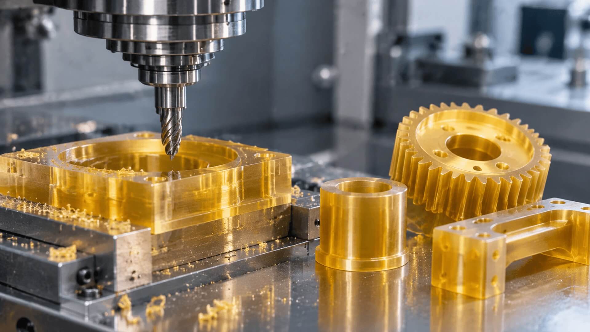
These physical properties make POM an essential material for precision spur gears, lead-screw nuts, fluid metering valves, medical delivery mechanisms, and electrical insulator housings.
However, subtractive CNC machining of Delrin introduces specific manufacturing challenges that cause yield losses in general machine shops.
Because POM is a semi-crystalline polymer with an extremely high coefficient of linear thermal expansion (CLTE ≈100 to120×10⁻⁶K, more than four times that of aluminum and ten times that of structural steel) and low thermal conductivity (~0.31 W/(m⋅K)), cutting heat generated during milling or turning cannot rapidly conduct into the workpiece core.
If cutting parameters allow tool rubbing or if clamping setups apply excessive compressive force, parts experience post-machining shrinkage, dimensional relaxation, and geometric warping days after leaving the machine fixture.
Furthermore, design engineers frequently treat POM as a single generic material callout, failing to differentiate between POM-C (acetal copolymer) and POM-H (acetal homopolymer, DuPont Delrin). This oversight leads to catastrophic field failures in leak-tight fluidic assemblies or premature tooth fracture in precision gearboxes.
Navigating these challenges requires strict parameter discipline, specialized cutter geometries, structured stress-relief workflows, and low-force metrology. Hardware development teams looking for certified aerospace, medical, or industrial acetal components can partner with Celerity Precision through our custom Delrin POM CNC machining services.
Table of Contents
POM-C (Copolymer) vs. POM-H (Homopolymer): The Machinability Breakdown
Specifying “Delrin” on an engineering drawing when a component requires generic acetal—or vice versa—is one of the most common material specification errors in precision manufacturing. POM exists in two distinct chemical formulations: POM-H (Homopolymer) and POM-C (Copolymer).
Molecular Architecture & Centerline Behavior
Material Selection MatrixPOM-H (Delrin Homopolymer)
High RigidityPOM-C (Acetal Copolymer)
Leak-Tight Choice1. Chemical and Mechanical Morphology
- POM-H (Homopolymer, e.g., Delrin 150, Delrin 500): Synthesized through the polymerization of formaldehyde, yielding a molecular chain consisting exclusively of repeating oxymethylene units ([−CH₂-O−]ₙ). This homogeneous linear structure enables tight crystalline packing, yielding a higher degree of crystallinity (75% to 85%). Consequently, POM-H exhibits higher tensile strength (approx. 72 MPa vs. 65 MPa for POM-C), roughly 10% to 15% higher flexural modulus, superior surface hardness (Rockwell M88 vs. M80), and higher fatigue endurance limits. It represents the preferred resin for heavily loaded structural gears, drive bushings, and high-impact mechanical components.
- POM-C (Copolymer, e.g., Celcon, Ultraform, Hostaform): Incorporates oxyethylene units ([−CH₂-CH₂-O−]) randomly distributed along the polymer backbone (typically 2% to 4% comonomer content). These carbon-carbon bonds disrupt regular crystalline folding slightly, resulting in lower baseline crystallinity (65% to 75%). However, these C-C bonds provide thermal and chemical stability against hydrolytic attack. POM-C resists strong alkalis (pH 4 to 14), resists degradation in continuous hot water applications up to 80°C (176°F), and experiences significantly less thermal degradation during repeated processing.
| Engineering Property | POM-C (Copolymer) | POM-H (Delrin Homopolymer) | Practical Machining & Application Impact |
|---|---|---|---|
| Tensile Strength at Yield | 65 – 68 MPa (9.4–9.8 KSI) | 70 – 75 MPa (10.1–10.8 KSI) | POM-H provides higher peak load-bearing limits before plastic elongation. |
| Flexural Modulus | 2,700 – 3,000 MPa | 3,100 – 3,600 MPa | POM-H delivers greater beam stiffness; thin walls deflect less under cutter loads. |
| Elongation at Break | 30% – 50% | 25% – 40% | POM-C exhibits higher post-yield ductility; lower notch sensitivity during threading. |
| Continuous Service Temp | -50°C to +100°C | -50°C to +90°C | POM-C maintains thermal stability in elevated-temperature environments. |
| Chemical Resistance (Alkaline) | Excellent (pH 4 to 14) | Poor to Fair (Degrades) | POM-C is mandatory for medical sanitization and alkaline cleaning washdowns. |
| Hot Water & Steam Resistance | Superior (Boiling water) | Moderate (Hydrolytic risk) | POM-C is preferred for beverage dispensing, plumbing, and sterilization valves. |
| Centerline Porosity | None (Dense Core) | Prevalent in Thick Stock | Critical: POM-C is mandatory for pressure manifolds; POM-H leaks along mid-plane axes. |
2. The Centerline Porosity Trap in POM-H
The most critical defect encountered when machining thick-section POM-H is Centerline Porosity.
During the commercial extrusion of thick Delrin rod and plate (typically stock thicknesses exceeding 25 mm / 1.0″), the material cools from the outside inward. The outer surface freezes rapidly into a dense, solid crystalline shell.
Because acetal shrinks by approximately 2% to 3% volumetrically as it transitions from a liquid melt to a dense crystalline solid, the still-molten interior of the slab is starved of volume.
In POM-H, this severe volumetric contraction creates a continuous longitudinal network of microscopic voids, spongy micro-pores, and tear fractures located along the central 20% to 30% core axis of the stock.
Cross-Sectional Centerline Porosity Profile in POM-H Slabs
Internal Defect Anatomy- The Fluidic Failure Mode: If a machinist mills a hydraulic valve block, pneumatic manifold, or vacuum chamber out of thick POM-H stock where internal fluid channels intersect this center plane, gas or liquid will weep through the porous micro-channels, causing permanent pressure leakage that cannot be sealed by O-rings.
- The Cleanliness / Biological Failure Mode: In medical diagnostic manifolds and food processing machinery, centerline porosity traps bacterial colonies, trace cleaning reagents, and process fluids, making sanitization impossible.
- The Manufacturing Directive: For any component requiring pressure containment, vacuum integrity, or fluid isolation, specify POM-C copolymer. Because POM-C crystallization proceeds more gradually and comonomer structures retard rapid crystal collapse, extruded POM-C plates and rods are uniform and non-porous from the skin to the core. Reserve POM-H exclusively for structural components (e.g., gears, rollers, structural brackets) where cross-sections remain in compression or where center stock is completely bored out.
Speeds, Feeds & Cutting Parameters
Delrin machines cleanly, producing smooth surface finishes when sheared with sharp cutting edges. However, its low thermal conductivity (0.31 W/(m⋅K)) and relatively low melting point (165°C for POM-C,178°C for POM-H) mean that improper parameter selection generates excessive frictional heat.
This thermal buildup causes local gumming, workpiece expansion, and heavy burr formation across peripheral breakout edges.
The primary operational rule is: maintain high feed rates and moderate-to-high surface speeds. Never allow a cutting tool to dwell or rub against the polymer face without taking an active chip.
| Machining Operation | Tooling Substrate / Coating | Speed (SFM) |
Speed (m/min) |
Chip Load / Feed (FPT / IPR) |
Radial (Ae) | Axial (Ap) |
|---|---|---|---|---|---|---|
| End Milling - Roughing Milling | Polished Solid Carbide (Uncoated) | 500 – 1,000 | 150 – 300 | 0.10 – 0.20 mm/tooth | 0.40 – 0.60 × D | 1.00 – 1.50 × D |
| End Milling - Finishing Milling | Polished Solid Carbide (Uncoated) | 800 – 1,400 | 240 – 425 | 0.03 – 0.08 mm/tooth | 0.05 – 0.15 × D | 0.50 – 1.00 × D |
| Slotting (Full Width) Milling | Polished Solid Carbide (2-Flute) | 400 – 800 | 120 – 240 | 0.06 – 0.12 mm/tooth | 1.00 × D (Full) | 0.50 – 0.75 × D |
| Precision Face Milling Milling | Polished Carbide / PCD Inserts | 800 – 1,500 | 240 – 450 | 0.12 – 0.25 mm/tooth | 0.60 – 0.80 × Cutter D | 1.00 – 2.50 mm |
| CNC Turning - Roughing Turning | Polished Carbide (CCGT) | 600 – 1,200 | 180 – 365 | 0.15 – 0.35 mm/rev | N/A | 1.50 – 4.00 mm |
| CNC Turning - Finishing Turning | Polished Carbide (DCGT) | 800 – 1,600 | 240 – 485 | 0.05 – 0.12 mm/rev | N/A | 0.25 – 0.75 mm |
| Standard Twist Drilling Drilling | Polished High-Helix Carbide | 200 – 400 | 60 – 120 | 0.10 – 0.25 mm/rev | Full Drill D | 1.00 – 2.00 × D (Peck) |
| Deep-Hole Drilling (>3D) Drilling | Parabolic Flute Carbide Drill | 150 – 300 | 45 – 90 | 0.08 – 0.18 mm/rev | Full Drill D | 0.50 – 1.00 × D (Peck) |
Tooling Physics & Long Stringy Chip Management
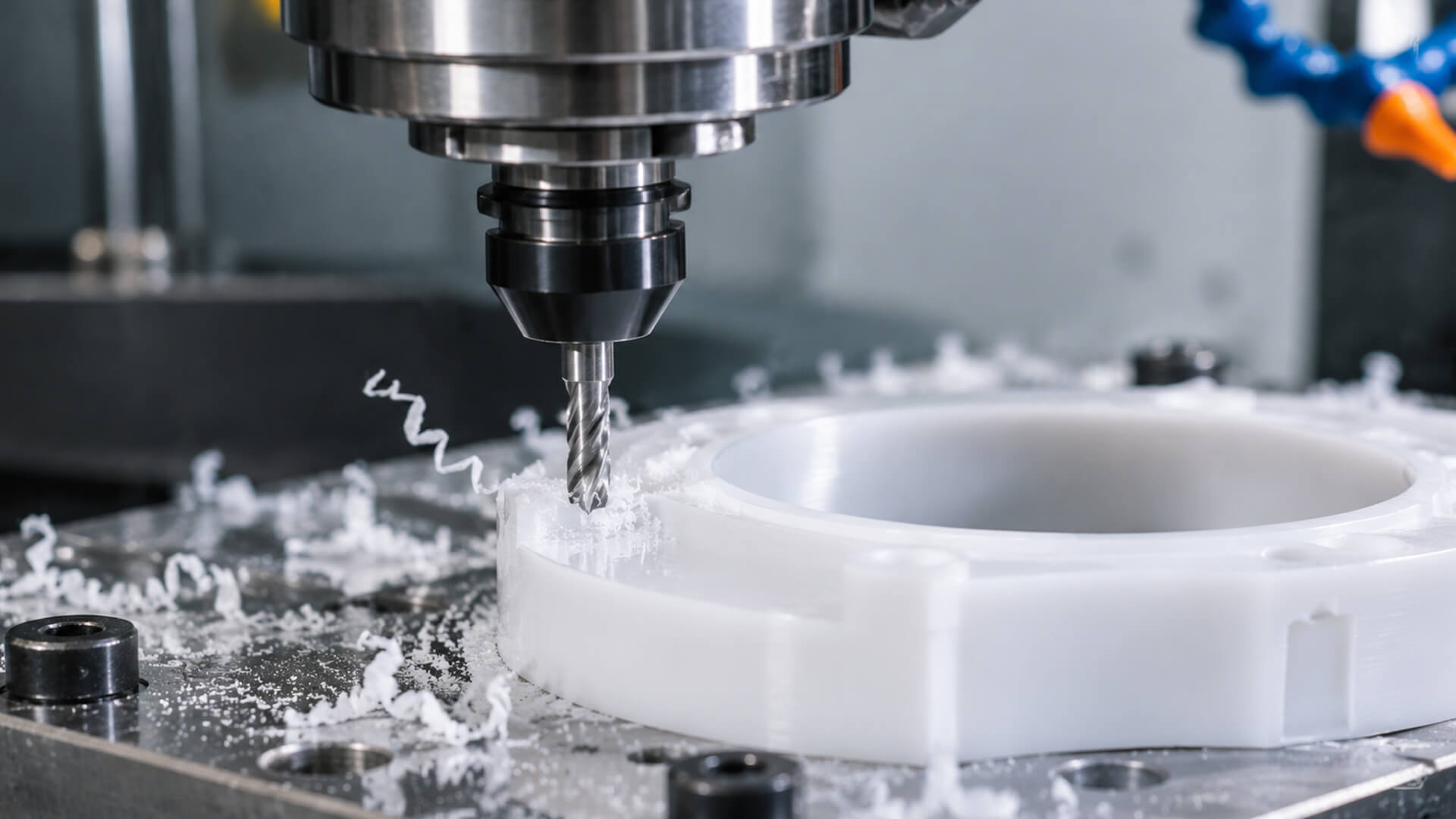
Standard cutting tools ground for ferrous alloys fail in Delrin production. Steel-cutting end mills feature micro-honed edge radii (15 to 25μm) and neutral or negative rake angles designed to withstand heavy shear forces. In POM, these dull cutting edges plow and compress the polymer, generating friction, expanding the cut face, and creating heavy, stringy burrs along every tool exit plane.
Optimized Cutter Geometry for Delrin / Acetal
Tooling Micro-Geometry Spec1. Tool Geometry Specifications
- Razor-Sharp Cutting Edges (rβ<3μm): Use ultra-fine sub-micron grain solid tungsten carbide tools left completely uncoated. Physical vapor deposition (PVD) coatings (such as AlTiN or TiAlN) are counterproductive; the deposition process rounds the cutting edge, increasing edge radius to over 10 µm. Mirror-polished, uncoated carbide maintains a clean edge radius under 3 µm, slicing cleanly through crystalline acetal chains without compressing the stock.
- Aggressive Positive Rake Angles (+15° to +20°): A high positive rake angle lifts and shears chips away from the parent stock with minimal cutting force, reducing heat generation in the primary shear zone.
- High Clearance Angles (+12° to +18°): High primary and secondary relief angles prevent the machined plastic face from elastically springing back against the clearance flank of the tool. Insufficient clearance leads to continuous frictional heating, thermal expansion, and dimensional taper.
- Flute Topography and Flute Count: When milling Delrin, use single-flute or two-flute end mills. Avoid 3-flute and 4-flute tools for pocketing and slotting; their small flute pockets trap continuous stringer chips, leading to chip re-cutting, frictional melting, and cutter breakage. Flutes must feature a mirror polish (Ra<0.05μm) to facilitate continuous chip evacuation.
2. Controlling Continuous Stringy Chips (“Bird’s Nesting”)
Delrin’s high tensile ductility and impact toughness prevent chips from naturally snapping into small, segmented curls during turning and drilling. Instead, the material forms tough, continuous ribbons.
In CNC lathes and machining centers, these continuous chips wrap around the tool shank, spindle nose, and workpiece, forming a dense tangle (“bird’s nest”). This chip mass scratches finished surfaces, damages toolholders, blocks coolant access, and breaks tools during automatic tool changes.
Mechanics of the Delrin “Bird’s Nest” Problem
Chip Evacuation DefectTo manage continuous stringer chips:
- Programmed Micro-Interruption Toolpaths: In CNC turning, utilize high-frequency tool oscillation cycles (chip-breaking macros). By oscillating the cutting tool along the feed axis, the feed rate drops to zero for milliseconds at calculated intervals. This oscillation mechanically cleaves the continuous ribbon into 15 mm to 30 mm segments that drop into the chip conveyor without wrapping around the tool.
- Controlled High-Pressure Air Blasts: Position directed nozzles blowing dry, filtered compressed air (or vortex-cooled cold air at 0°C to -5°C) directly at the tool-chip interface. The kinetic momentum of the air stream curls chips away from the tool shank, clearing them into the extraction chute.
- Modified Peck Drilling Cycles: In holemaking, never execute a continuous drilling feed deeper than 2×D. Program high-speed chip-breaking peck cycles (G73) for shallow holes, or full-retract peck cycles (G83) for depths exceeding 3×D. Full retraction out of the hole pulls out tangled stringers, clearing the bore before the drill re-enters.
3. Cooling Strategies: Flood Coolant vs. Vortex Cold Air
- The Precision Requirement for Flood Coolant: When machining tolerances tighter than ±0.025 mm (±0.001″), water-soluble flood coolant is mandatory. Dry machining generates localized thermal expansion (100×10⁻⁶/K). A bore machined dry may measure accurately while warm on the machine bed, but will shrink significantly once cooled to ambient inspection room temperature (20°C). Use clean, mineral-oil-free water-soluble synthetic emulsions mixed at 6% to 8% concentration to stabilize temperatures.
- Cold-Air Guns for Medical and Electronics Components: If parts are designated for cleanroom medical fluid paths or semiconductor vacuum handling where fluid residue is prohibited, run dry with high-velocity vortex cold-air guns. Avoid pure dry machining without an air stream; uncooled tools trap localized heat that accelerates burr formation.
Controlling Dimensional Stability & Warpage Prevention
The primary complaint among engineers sourcing CNC-machined Delrin is post-machining distortion. Parts that meet print dimensions immediately upon unclamping often warp, bow, or shrink out of tolerance within 24 to 48 hours.
This dimensional movement stems from two distinct physical sources: as-extruded residual skin stresses and clamping-induced elastic deflection.
As-Extruded Residual Stress Profile in Raw Delrin Plates
Residual Stress Dynamics1. Relieving Raw Material Extrusion Stresses
Extruded acetal plates and rods feature high residual compressive stresses locked within their frozen outer skins, balanced by internal tensile stresses in the core.
If a machinist takes a 25 mm thick plate and mills a 10 mm deep pocket entirely from one side, the compressive skin on that face is removed. The balanced stress system collapses, and the residual stresses in the remaining stock cause the component to bow upward.
- Symmetrical Stock Removal: When machining precision Delrin parts from plate stock, skim equal amounts of material from opposing faces. If 6 mm of total thickness must be removed, face off 3 mm from side A, flip the plate, and face off 3 mm from side B. Equal skin removal balances internal stress vectors, keeping the component flat.
- Intermediate Thermal Stress-Relief Annealing: For complex, asymmetrical components with tolerances under ±0.010 mm, execute a two-stage machining process with an intermediate stress-relief anneal:
- Rough-machine the part, leaving 0.50 mm to 0.75 mm of stock across all critical dimensions.
- Heat the semi-machined parts in an air-circulating oven at a ramp rate of +10°C to +15°C/hr up to 160°C (320°F)—approximately 10°C to 15°C below the melting point.
- Hold at 160°C for 30 minutes per 6 mm (0.25″) of wall section thickness to relax the crystalline matrix.
- Cool slowly within the sealed oven at a controlled rate not exceeding 10°C/hr down to 40°C. Opening the oven door prematurely creates a thermal shock gradient that induces new internal stresses.
- Perform light, sharp finish-machining passes to bring dimensions to print.
2. Workholding Without Elastic Compressive Distortion
Delrin has an elastic modulus of ~3.0 GPa—roughly 4% of aluminum’s stiffness (~70 GPa). When clamped in a standard machine vise with serrated steel jaws, the clamping force compresses the polymer elastically.
The part is machined flat and parallel while compressed; but as soon as the vise jaws open, the part springs back, resulting in bowed faces, out-of-round bores, and non-parallel datum planes.
Vise Clamping Elastic Deformation Trap
Fixturing & Workholding DefectTo eliminate clamping distortion:
- Custom Contoured Aluminum Soft Jaws: Machine matching negative cavities into aluminum soft jaws or wrap-around 360-degree pie jaws on CNC lathes. Spreading clamping pressure across large surface areas reduces localized contact stress, holding the component securely with light clamping pressure.
- Vacuum Chuck Fixturing: For flat plates, thin-wall electronic housings, and fluid manifolds, use porous ceramic vacuum chucks. Vacuum workholding applies uniform downward atmospheric clamping force (~1 bar / 14.7 PSI) across the entire component face, eliminating mechanical distortion.
- Dedicated Multi-Stage Semi-Finishing Passes: In turning thin-walled bushings (<2.0 mm wall thickness), rough out the outside and inside diameters, unclamp the part completely to let the plastic relax to its natural shape, re-clamp under light holding torque, and execute light finishing passes (0.1 to0.2 mm depth of cut).
Precision Machining on Celerity Shop-Floor Equipment
Delrin’s ductility and low thermal conductivity require high spindle speeds, fast dynamic acceleration, and rigid machine platforms to maintain tight production tolerances.
At Celerity Precision, Delrin components are routed across dedicated, high-speed machine cells:
1. Ultra-High-Speed Micro-Milling (Beijing Jingdiao JDGR200T)
Machining miniature POM drive gears (Module 0.2 to 0.8), micro-fluidic channels, and fine-pitch electrical connectors requires high spindle RPM combined with low tool runout to prevent edge burring:
- 24,000 RPM Direct-Drive Spindles: Our Beijing Jingdiao JDGR200T 5-axis machining centers feature high-speed electro-spindles with dynamic runout verified under 0.001 mm (0.00004″).
- Burr-Free Micro-Tooth Form Generation: Operating at 24,000 RPM allows micro-end mills down to 0.2 mm diameter to cut at their optimal surface speeds (SFM). High-speed shearing slices through crystalline POM spherulites without pulling or smearing material, producing mirror-like tooth profiles and sharp corner transitions without secondary deburring.
2. High-Speed Production Kinematics (Fanuc Robodrill & Makino a40)
For mid-to-high volume production runs of valve housings, bearing cages, and consumer hardware:
- Dynamic Axis Acceleration (1.5G Acceleration): Our Fanuc Robodrill platforms provide 1.5G axis acceleration and 54 m/min rapid traverse rates. High acceleration allows cutters to maintain programmed feed rates without decelerating in corners, preventing localized dwelling and thermal friction.
- Horizontal Structural Stability: For multi-sided manifold blocks, our Makino a40 horizontal machining centers utilize rigid stepped-column castings and direct-drive rotary tables. Machining horizontally allows heavy POM chip streams to drop away under gravity, preventing the re-cutting of hot chips.
To review our complete production facilities, explore our precision CNC turning services and custom CNC milling capabilities.
Precision Inspection & Quality Assurance Standards
Verifying micro-tolerances on Delrin components requires inspection protocols tailored to soft, thermally sensitive engineering polymers.
1. Zeiss CMM Low-Force Contact Probing
Dimensional verification of tight-tolerance bores, hole locations, and geometric dimensioning and tolerancing (GD&T) callouts is conducted inside our dedicated metrology laboratory, maintained at a continuous 20°C ± 1°C (68°F ± 1.8°F).
- Thermal Soak Stabilization: Because Delrin exhibits high thermal expansion, all components rest inside the metrology room for a minimum of 4 to 8 hours before inspection until internal core temperatures stabilize at 20°C.
- Low-Force Probing Calibration: Contact measurements are performed on our bridge-type Zeiss CMM. Contact trigger forces are calibrated to under 0.05 N (5 grams) using micro-stylus configurations. Standard coordinate measuring machine touch probes configured for steel inspection (0.2 N to 0.5 N) can indent the soft Delrin surface elastically, creating false out-of-spec readings. Verified spatial measurements achieve ±0.005 mm (±0.0002″).
2. Non-Contact Optical Inspection via Automatic Vision Measuring Systems (VMM)
For micro-gears, thin-walled medical delivery components, and elastomeric seal retention grooves where physical contact deflection compromises accuracy:
- Automatic Image Measuring Instrument: Celerity Precision deploys high-resolution non-contact Vision Measuring Machines (VMM).
- Optical Edge Detection: Sub-pixel telecentric optical lenses and programmable multi-angle LED ring illumination map complex 2D and 3D profiles without physical contact. Gear pitch circles, involute form deviations, and edge radii are verified optically without mechanical deflection.
3. Material Lot Verification: XRF Spectroscopy & Density Verification
A persistent supply chain issue is the substitution of uncertified recycled regrind material or off-spec generic acetal resins for genuine DuPont Delrin 150/500 or certified POM-C. Regrind resin degrades molecular chain length, lowering impact resistance, accelerating cyclic fatigue failure, and inducing inconsistent thermal shrinkage during machining.
Celerity Precision verifies incoming raw bar, rod, and sheet material through a two-stage quality protocol:
- Chemical Composition Screening via XRF: Every incoming raw material heat undergoes non-destructive inspection via an on-site X-Ray Fluorescence (XRF) Spectrometer / Analyzer to screen for heavy metal impurities, non-compliant plasticizers, and unauthorized fillers.
- Precision Gravimetric Density Testing: Polymer density is verified via immersion displacement metrology against ASTM D792 standards (confirming 1.41 to 1.42 g/cm³ for POM-C and 1.42 to 1.43 g/cm³ for POM-H). Material test reports (MTRs) are matched with resin batch certifications, guaranteeing 100% prime virgin resin for every production run.
DFM Rules for Cost-Effective Delrin Parts
Delrin is an economical, high-performance material, but poor Design for Manufacturability (DFM) drives up unit costs through extended cycle times, specialized tooling requirements, and scrap rates caused by warpage.
Applying these four design rules helps balance functional performance with practical manufacturing costs:
1. Maintain Uniform Wall Thicknesses (≥ 1.0 mm to 1.5 mm)
Extremely thin unsupported walls (<0.8 mm) flex away from cutting tools during milling passes. This deflection causes wall taper, surface chatter, and micro-cracking along base fillets.
- DFM Rule: Design structural walls with a nominal thickness between 1.50 mm and 3.00 mm. Maintain uniform thickness across the part to prevent differential stress cooling. Where thin ribs are necessary, incorporate a 1° to 2° draft angle and support them with gusset structures to resist tool-push forces.
2. Radiused Internal Pocket Corners (R ≥ 1.0 mm)
Designing sharp, 90-degree internal vertical corners forces machine shops to deploy micro-end mills. Micro-cutters run at reduced feed rates and deflect easily, while sharp internal corners act as stress concentrators where notch-sensitive acetal parts can fracture under impact loads.
- DFM Rule: Design internal corner radii to at least R≥1.00 mm (0.040″), and ideally R≥1.5× tool radius. Generous internal fillets allow rigid, larger-diameter end mills to machine pockets at high feeds without pausing or chattering in the corners.
3. Thread Engagement Depth Guidelines (2.0 to 2.5 × Diameter)
Tapping Delrin requires care. Because the material possesses a lower shear modulus than metals, specifying short thread engagement depths (1.0×D) leads to thread stripping under moderate tensile bolt torques.
Conversely, designing threads smaller than M2.5 or specifying direct fine-pitch threads increases tool breakage risk during tapping.
- DFM Rule: Specify internal thread engagement depths between 2.0×D and 2.5×D to provide adequate shear engagement. Where frequent field assembly and disassembly are required, design pockets for brass threaded inserts (ultrasonically staked or heat-staked) rather than tapping directly into the raw plastic.
4. Symmetrical Geometry and Balanced Core Relief
Designing asymmetric solid parts with deep, non-uniform pockets cleared from only one side releases extrusion skin stresses unevenly, causing the component to bow along its length.
- DFM Rule: Design components with balanced material removal across opposing faces. Where thick sections are unnecessary for mechanical loading, core out the geometry symmetrically from both sides, leaving supporting structural ribs. Cored geometries reduce raw material consumption, speed up cycle times, and minimize post-machining warpage.
Precision Delrin Component Sourcing & Production
Machining Delrin (POM-C and POM-H) to tight tolerances requires moving past basic plastic-cutting practices. Repeatable tolerances demand an integrated manufacturing approach: choosing the correct resin formulation (copolymer vs. homopolymer), deploying razor-sharp uncoated tooling, managing stringy chips, using balanced stress-relief thermal cycles, and verifying dimensions with low-force Zeiss CMM and optical vision systems.
Whether your application calls for miniature, burr-free gear assemblies manufactured on our custom CNC milling centers or high-volume precision bushings produced via our precision CNC turning services, Celerity Precision delivers repeatable, tight-tolerance components backed by material certifications and inspection reports.
Request a Comprehensive DFM Analysis and Precision Delrin Quote
Submit your 3D CAD models (STEP, IGS) and 2D engineering drawings to our plastics application engineering team. We will deliver an engineering-grade manufacturability review within 24 hours, evaluating centerline porosity risks, clamping strategies, stress-relief requirements, and transparent factory-direct pricing.
- Strict Non-Disclosure Agreement (NDA) Protection
- 24-Hour Engineering DFM & Quotation Turnaround
- Zeiss CMM Low-Force Probing & Vision System Dimensional Inspection
Upload your CAD files via our contact page to begin your project review with our engineering team.

CP Engineering Team
Authored and peer-reviewed by the Senior Engineering and Metrology Team at Celerity Precision. Backed by German 5-axis CNC machining centers, high-speed micro-milling platforms, and a climate-controlled Zeiss CMM inspection lab, our team delivers deep DFM insights, material machinability guides, and precision manufacturing solutions for aerospace, medical, and semiconductor developers worldwide.