Machining Kovar & Invar 36: Cutting Speeds, Tooling, Thermal Expansion & Deburring Guide

Controlled expansion alloys—principally Kovar (ASTM F15, UNS K94610) and Invar 36 (UNS K93600, Werkstoff 1.3912)—occupy a critical niche in advanced manufacturing. Engineered specifically for applications where mechanical dimensions must remain stable across fluctuating thermal environments, or where metal components must fuse directly to brittle non-metallic substrates without generating destructive shear strains, these iron-nickel and iron-nickel-cobalt formulations are indispensable.
Kovar is an iron-nickel-cobalt alloy containing nominally 29% nickel, 17% cobalt, and 54% iron. Its thermal expansion profile non-linearly matches the thermal expansion curves of borosilicate hard glasses (such as Corning 7052 and Schott 8250) and high-purity alumina ceramics from cryogenic temperatures up to approximately 450°C (842°F). This matching Coefficient of Thermal Expansion (CTE ≈5.1 to5.5×10⁻⁶/K between 20°C and 400°C) allows engineers to produce hermetic, vacuum-tight glass-to-metal and ceramic-to-metal feedthrough seals for microwave packages, optoelectronic photodetectors, defense radar modules, and aerospace vacuum assemblies.
In contrast, Invar 36 is a binary solid-solution alloy containing 36% nickel and 64% iron. It relies on the “Invar effect”—a quantum-magnetic phenomenon where spontaneous magnetostriction precisely counteracts normal crystallographic thermal expansion below its Curie temperature (Tc≈280∘C). This mechanism yields a near-zero Coefficient of Thermal Expansion (CTE ≈1.2×10⁻⁶/K between -100°C and +200°C), roughly one-tenth that of structural carbon steel. Invar 36 serves as the primary structural material for satellite optical benches, high-stability laser cavity spacers, cryogenic waveguides, astronomical shadow masks, and precision metrology positioning stages.
However, from a CNC machining perspective, Kovar and Invar 36 present severe manufacturing challenges.
Both alloys exhibit fully austenitic face-centered cubic (FCC) crystal structures characterized by high tensile elongation (often exceeding 35% to 40%), poor thermal conductivity ( ~10.5 to17 W/(m⋅K)), high shear strength, and rapid work hardening.
During metal cutting, they behave as extremely “gummy” materials: long, ductile chips fail to break naturally, adhering chemically to the tool face to form severe Built-Up Edge (BUE) deposits.
Simultaneously, mechanical shearing locks high tensile residual stresses into the sub-surface layers of the part, altering its native thermal expansion curve and degrading magnetic permeability unless controlled stress-relief protocols are applied.
Navigating these challenges requires specialized tooling, disciplined speeds and feeds, high-pressure extreme-pressure lubrication, and multi-axis machine rigidity. Hardware development teams looking for certified aerospace, optoelectronic, and defense components can partner with Celerity Precision through our custom CNC machining capabilities.
Table of Contents
The Machinability Nightmare: Ductility, Gummy Chips & Work Hardening
Machining Kovar or Invar 36 is often described by CAM programmers as combining the abrasive tool-wear mechanics of high-nickel superalloys with the extreme gumminess and chip-welding tendencies of soft austenitic stainless steels (such as 304 or 316).
With a relative machinability rating of only 35% to 40% (benchmarked against free-machining AISI 1212 steel at 100%), successful cutting requires addressing three distinct physical failure modes:
1. Severe Built-Up Edge (BUE) and Adhesive Galling
Due to their high nickel content and low thermal conductivity, cutting interface temperatures rapidly exceed 650°C (1,200°F). At these temperatures, the ductile, gummy alloy sticks and pressure-welds directly onto the rake face and cutting edge of the tool.
Mechanics of Built-Up Edge (BUE) Failure
Tool-Chip Adhesive DefectAs the BUE deposit grows, it effectively alters the tool’s rake geometry, dulling the edge and increasing cutting forces.
Eventually, the hydrodynamic flow of chips tears the BUE fragment away from the tool.
Because the weld bond between the nickel alloy and the cutting tool is exceptionally strong, this fracture pulls sub-micron cobalt and tungsten carbide grains directly out of the tool substrate. This cyclical adhesive wear produces rapid edge chipping, micro-cratering, and severe surface tearing on the machined component.
2. High Strain Hardening and the “Depth-of-Cut” Notch Trap
Kovar and Invar 36 possess high work-hardening exponents ( n≈0.35 to 0.45). When the cutting tool passes through the shear zone, localized plastic deformation strain-hardens the surface layer, increasing micro-hardness from an annealed state of approximately 140–160 HB up to 320–360 HB.
If a machine operator attempts to take light “dusting” or skim passes (ap<0.10 mm or fz<0.025 mm/tooth), the cutting edge rubs against this work-hardened deformation layer rather than cleanly shearing beneath it.
This causes immediate flank wear, generating intense frictional heat that deepens the work-hardened zone.
Furthermore, where the cutting edge contacts the outer edge of the cut (the depth-of-cut line), severe notch wear (V-shaped localized grooving) forms on the tool flank, destroying the tool edge.
3. Extremely Poor Thermal Dissipation
The thermal conductivity of Kovar ( ∼17.3 W/(m⋅K)) and Invar 36 (∼10.5 W/(m⋅K)) is lower than titanium Grade 5 (~6.7 to 8.0 W/(m·K)) and far below 6061-T6 aluminum (~160 W/(m·K)).
Because thermal energy cannot dissipate into the core of the workpiece, more than 75% of the cutting heat concentrates within a contact zone less than 0.5 mm wide along the cutting edge.
Without targeted high-pressure lubrication, this heat spike rapidly softens tool coatings, triggers cobalt leaching, and induces localized dimensional distortion that invalidates in-process CMM metrology.
Physical Properties & Speeds, Feeds Parameter Tables
Achieving tight tolerances in Kovar and Invar requires establishing a stable mechanical baseline by comparing their fundamental physical properties against standard aerospace materials.
| Physical & Mechanical Property | Kovar ASTM F15 | Invar 36 FeNi36 | 304 Stainless Ref | Practical Machining & Engineering Impact |
|---|---|---|---|---|
| Nominal Chemical Composition | 29% Ni, 17% Co, Bal. Fe | 36% Ni, 0.3% Mn, Bal. Fe | 18% Cr, 8% Ni, Bal. Fe | High Ni/Co content drives extreme adhesive gumminess and rapid chemical tool wear. |
| Coefficient of Thermal Expansion (20°C–400°C) | 5.1 – 5.5 ppm/°C (Matches Glass) | 1.2 – 2.0 ppm/°C (Near-Zero CTE) | 17.3 – 18.5 ppm/°C (High CTE) | Critical: Invar maintains absolute spatial scale; Kovar prevents glass seal cracking during cooldown. |
| Thermal Conductivity (at 20°C) | 17.3 W/(m·K) | 10.5 W/(m·K) | 16.2 W/(m·K) | Low thermal dissipation traps 75%+ of cutting heat directly at the cutting edge. |
| Tensile Strength (Annealed) | 520 – 550 MPa (75–80 KSI) | 480 – 520 MPa (70–75 KSI) | 515 – 620 MPa (75–90 KSI) | Moderate bulk strength, but high dynamic shear resistance under heavy chip loads. |
| Yield Strength (0.2% Offset) | 340 – 380 MPa (49–55 KSI) | 240 – 280 MPa (35–40 KSI) | 205 – 240 MPa (30–35 KSI) | High yield strength requires rigid machine kinematics to prevent dynamic chatter. |
| Elongation at Break (%) | 30% – 40% | 35% – 45% | 40% – 55% | Extreme ductility causes continuous ribbon chips and stubborn exit burrs. |
| Machinability Rating (% of 1212) | ~35% – 40% | ~35% – 40% | ~45% | Low rating requires 50%+ reduction in cutting line speed versus carbon steel. |
Industrial Cutting Speeds & Feeds Parameter Table
The primary rule when cutting Kovar and Invar 36 is: moderate surface cutting speeds, positive continuous chip loads, and generous depths of cut.
Never allow the tool to dwell or burnish. The cutting edge must bite cleanly beneath the strain-hardened layer left by the preceding pass.
The parameter matrix below outlines validated starting parameters across annealed Kovar and Invar 36:
| Machining Operation | Tooling Substrate & Coating | Speed (SFM) |
Speed (m/min) |
Chip Load / Feed (FPT / IPR) |
Radial (Ae) | Axial (Ap) |
|---|---|---|---|---|---|---|
| End Milling - Roughing Milling | Sub-micron Carbide (PVD TiCN) | 120 – 180 | 36 – 55 | 0.04 – 0.08 mm/tooth | 0.30 – 0.50 × D | 0.75 – 1.25 × D |
| End Milling - Finishing Milling | Sub-micron Carbide (PVD AlCrN) | 160 – 240 | 48 – 75 | 0.02 – 0.04 mm/tooth | 0.05 – 0.10 × D | 0.50 – 1.00 × D |
| Slotting (Full Width) Milling | Sub-micron Carbide (3-Flute) | 90 – 140 | 28 – 42 | 0.03 – 0.06 mm/tooth | 1.00 × D (Full) | 0.25 – 0.50 × D |
| Precision Face Milling Milling | Indexable Inserts (TiCN/TiAlN) | 140 – 220 | 42 – 68 | 0.08 – 0.15 mm/tooth | 0.60 – 0.75 × Cutter D | 1.00 – 2.00 mm |
| CNC Turning - Roughing Turning | Tough ISO Carbide (CNMG/WNMG) | 130 – 200 | 40 – 60 | 0.15 – 0.25 mm/rev | N/A | 1.50 – 3.00 mm |
| CNC Turning - Finishing Turning | Sharp ISO Carbide (CCGT/DCGT) | 180 – 280 | 55 – 85 | 0.04 – 0.08 mm/rev | N/A | 0.25 – 0.60 mm |
| Twist Drilling (Carbide) Drilling | Polished Parabolic Solid Carbide | 80 – 140 | 25 – 42 | 0.04 – 0.08 mm/rev | Full Drill D | 0.50 – 1.00 × D (Peck) |
| Thread Milling (Single/Multi) Recommended | Solid Carbide Thread Mill (TiCN) | 100 – 150 | 30 – 45 | 0.02 – 0.04 mm/tooth | Full Thread Profile | Profile Pitch Step |
Tooling Physics & Cutting Fluid Selection
Applying generic tooling geometry or unlubricated cutting conditions to Kovar or Invar guarantees rapid failure. Tooling must combine high fracture toughness with geometries that minimize adhesive friction.
Optimized Cutter Geometry for Kovar & Invar 36
Tooling Micro-Geometry Spec1. Tooling Substrates: Why Ceramics Are Strictly Banned
- Ultra-Fine Sub-Micron Tungsten Carbide: Tooling must utilize premium sub-micron grain solid carbide (WC) bound with 10% to 12% cobalt (Co). A higher cobalt content provides the transverse rupture strength (TRS > 4,200 MPa) required to withstand mechanical shock loads when chips tear away from the edge.
- Avoid Ceramics and CBN: Although whisker-reinforced ceramics operate well in high-speed Inconel roughing, they fail completely in Kovar and Invar. The high ductility and severe adhesive friction of controlled expansion alloys generate high tensile edge stresses that chip brittle ceramic substrates within seconds.
2. Advanced PVD Coating Chemistry
Thick CVD coatings must be avoided; the chemical vapor deposition process blunts the cutting edge (increasing edge radius rβ>15μm) and introduces tensile residual stresses that encourage chipping. Instead, specify thin (2 to 4 µm), low-stress Physical Vapor Deposition (PVD) films:
- PVD TiCN (Titanium Carbonitride): TiCN provides a high surface micro-hardness (~3,000 HV) paired with an exceptionally low coefficient of friction (μ≈0.35 against steel). The carbon content acts as an integrated solid lubricant, minimizing adhesive galling, preventing BUE formation, and extending tool life during turning, slotting, and thread milling.
- PVD AlCrN (Aluminum Chromium Nitride): For high-speed finish milling, AlCrN coatings provide thermal stability up to 1,100°C (2,012°F). The chromium oxide barrier layer prevents atomic diffusion between the nickel/cobalt workpiece and the carbide tool.
3. Micro-Geometries & Edge Preparation
- Positive Rake Angles (+8° to +12°): Slices through ductile nickel fibers cleanly, reducing specific cutting forces (kc≈2,400 N/mm²) and minimizing deformation-induced work hardening.
- Generous Primary Relief (+10° to +14°): Eliminates friction caused by the elastic springback of the austenitic matrix against the tool flank.
- Precision Micro-Honed Edge (rβ=5 to 10μm): A dead-sharp unhoned edge (rβ<2μm) will micro-chip under dynamic shock loads. The cutting edge must feature a controlled, light micro-hone or waterfall hone to stabilize the cutting wedge without generating plowing forces.
- Flute Topography: Milling tools must feature mirror-polished flutes (Ra<0.05μm) to facilitate smooth chip evacuation and prevent continuous ribbons from clogging the cutter.
4. Coolant Discipline & Extreme Pressure Lubrication
Dry machining of Kovar and Invar 36 is strictly prohibited. Without constant lubrication, the tool edge will overheat, gall, and weld to the component.
- High-Concentration Water-Soluble Emulsions: In standard milling, use premium synthetic or semi-synthetic water-miscible fluids equipped with active extreme-pressure (EP) chlorinated or ester-based boundary additives. While aluminum runs at 6% concentration, Kovar and Invar require a concentration of 10% to 12%. High concentration creates a boundary lubricating film that reduces friction across the secondary shear zone.
- Dedicated Neat Cutting Oils for Tapping and Threading: Tapping blind holes smaller than M4 in Kovar using standard coolant frequently results in broken taps. For hole-tapping, threading, and deep-hole drilling, flood the interface with heavy-duty sulfurized and chlorinated neat cutting oils. Active sulfur compounds react chemically with the iron-nickel surface, forming a solid iron-sulfide boundary layer that mechanically prevents chip welding under high localized contact pressures.
The Critical Post-Machining Annealing Cycle
One of the most consequential metallurgical errors in precision manufacturing is failing to execute a post-machining stress-relief and magnetic anneal.
Machining operations—even with sharp tools and light passes—distort the crystal lattice within the outer 0.05 mm to 0.15 mm of the component.
In controlled expansion alloys, plastic strain, micro-twinning, and residual tensile stresses disrupt the spontaneous magnetic domain alignment that produces the Invar effect.
The immediate consequences of unannealed machining stresses are:
- Destruction of the Low-Expansion Curve: Residual shear stresses shift the alloy’s Curie point (Tc) and elevate the room-temperature Coefficient of Thermal Expansion. An Invar 36 part that should measure 1.2 ppm/°C can exhibit a CTE exceeding 3.5 to 5.0 ppm/°C, ruining optical alignment in satellite payloads.
- Loss of Magnetic Permeability: In RF shielding and magnetic sensor enclosures, cold-working reduces initial and maximum magnetic permeability (μr) by up to 80%, destroying electromagnetic attenuation capability.
- Delayed Micro-Warping: High residual tensile stresses slowly relax over time, causing finished components to twist, bow, or lose sub-micron flatness months after installation.
Kovar & Invar 36 High-Vacuum Hydrogen Annealing Profile
Magnetic & CTE RestorationTo restore the material’s native CTE curve and maximize magnetic permeability, components must undergo a controlled hydrogen atmosphere annealing thermal cycle:
1. Two-Stage Manufacturing Workflow
Rough-machine the component across all datums, leaving 0.30 mm to 0.50 mm (0.012″ to 0.020″) of finish stock allowance on critical mating faces, bores, and seal planes. Never attempt to achieve final ±0.005 mm dimensions prior to annealing; the thermal cycle will relieve residual stresses and induce minor volumetric movement.
2. The Hydrogen Decarburization & Stress-Relief Cycle
- Atmosphere: The annealing furnace must operate under a protective atmosphere of pure dry hydrogen (H₂) with a dew point below -40°C (-40°F), or under high vacuum (<10⁻⁴ Torr) with a dry hydrogen backfill. Hydrogen reduces surface oxides, removes trace interstitial carbon (which alters expansion curves), and prevents surface scaling.
- Heating and Soak Phase: Ramp temperature at a controlled rate of +150°C to +200°C/hr up to 1,000°C to 1,050°C (1,832°F to 1,922°F) for Kovar, or 850°C to 900°C (1,562°F to 1,652°F) for Invar 36. Soak at peak temperature for 1 to 2 hours to recrystallize deformed grains and fully relieve residual lattice strains.
- Controlled Slow Cooling: Cooling rate through the critical Curie transition zone is paramount. Cool slowly inside the furnace at a rate not exceeding 100°C/hr down to 500°C, followed by 200°C/hr down to 200°C, before cooling to room temperature. Rapid quenching freezes in thermal stresses, defeating the purpose of the cycle.
- Final Light Skim Finishing: Re-fixture the annealed components and execute light finishing passes (aₚ≤0.10 mm, razor-sharp polished carbide, copious flood coolant) to bring functional dimensions and sealing faces to print tolerances.
Shop-Floor Capabilities: Celerity’s High-Precision Centers
Machining Kovar and Invar 36 without burr formation or micro-cracking requires dynamic machine tool rigidity, precise spindle runout, and multi-axis flexibility.
At Celerity Precision, controlled expansion components are manufactured across dedicated machining cells:
1. Burr-Free Micro-Milling & Micro-Hole Generation (Beijing Jingdiao JDGR200T)
Kovar components utilized in hermetic microwave packaging frequently feature hundreds of tightly spaced micro-feedthrough holes ( Φ0.5 mm to 1.5 mm) and thin sealing lips (<0.5 mm
width) where deburring with hand tools is prohibited:
- 4,000 RPM High-Speed Electro-Spindles: Our Beijing Jingdiao JDGR200T high-speed machining centers utilize direct-drive spindles with dynamic radial runout verified under .001 mm (0.00004″).
- Micro-Grain Shearing: Operating at high RPM enables micro-end mills down to 0.3 mm diameter to maintain proper surface cutting speeds. The combination of high-speed kinematics and ultra-low runout slices cleanly through ductile Kovar fibers, suppressing exit burr formation and eliminating manual bench deburring that risks damaging delicate glass-sealing edges.
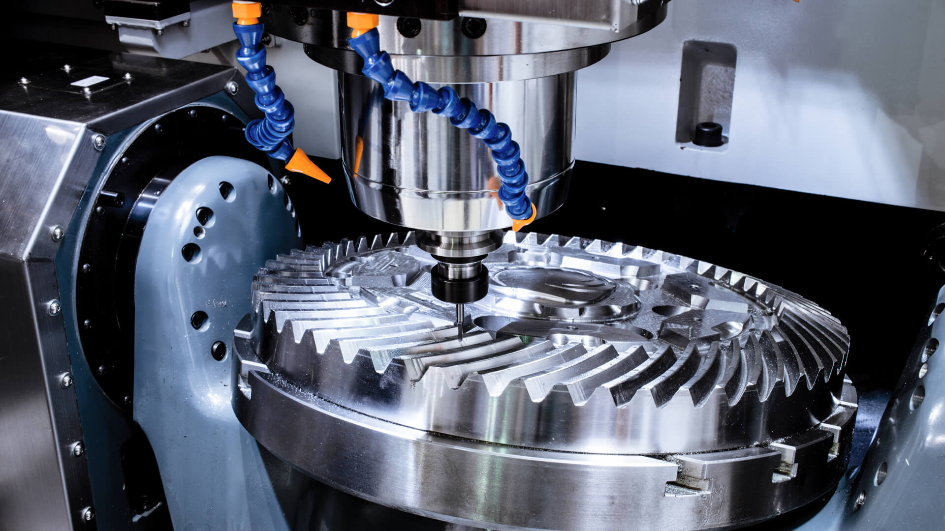
2. Single-Setup Complex 5-Axis Profiling (German Hermle C400)
Optoelectronic bench chassis, satellite sensor housings, and laser mirror frames feature complex geometry requiring multi-angle porting and tight true-position tolerances:
- Eliminating Multi-Clamping Errors: Re-clamping gummy alloys multiple times introduces cumulative datum stack-up errors and induces clamping-induced residual strains. On our German Hermle C400 5-axis CNC machining centers, multi-sided housings are fully machined in a single clamping setup.
- Mineral-Cast Polymer Concrete Damping: The Hermle C400 utilizes a mineral-cast base with structural vibration damping up to 10 times higher than gray cast iron. This dynamic damping absorbs high-frequency vibrations induced by adiabatic shear banding in nickel alloys, preventing chatter and extending carbide tool life by up to 200%.
To review our complete production facilities, explore our precision CNC milling services.
Precision Metrology & Metallurgical Integrity
Verifying aerospace and optoelectronic components machined from Kovar and Invar 36 requires specialized metrology workflows tailored to controlled expansion metallurgy:
1. Zeiss CMM Dimensional Inspection
Spatial dimensional verification is conducted in our dedicated metrology laboratory, maintained at a continuous 20°C ± 1°C (68°F ± 1.8°F):
- The Metrology Metadynamics of Invar: While Invar 36 features near-zero thermal expansion, the granite bed, steel scales, and mechanical drive mechanisms of the CMM do expand and contract with ambient temperature. Maintaining a stable 20°C environment ensures that machine scale compensation matches true spatial dimensions.
- Low-Force Scanning Probing: Contact inspection is performed using our bridge-type Zeiss CMM equipped with high-accuracy scanning probes. Complex 3D contours, sealing perimeter flatnesses (<0.005 mm), and hole-to-hole true positions are verified down to ±0.005 mm (±0.0002″).
- Non-Contact Vision Metrology: Delicate glass-sealing perimeters, micro-pin arrays, and sharp knife-edge transitions are mapped using high-resolution automated vision measuring machines (VMM) to prevent probe deflection errors.
2. Raw Material Lot Verification via XRF Spectroscopy
A critical failure mode in hermetic packaging is receiving off-spec or mislabeled raw material. If an alloy labeled as Kovar deviates by even 0.5% in its nickel or cobalt balance, its thermal expansion curve will diverge from borosilicate glass.
When the assembly is fired in the glassing furnace at 1,000°C and cooled, the mismatched contraction rates generate high interfacial shear stresses that crack the glass meniscus, destroying vacuum hermeticity.
XRF Spectrometer Verification Protocol
Material Pedigree QA / ASTM F15• Nickel (Ni): 29.0% ± 0.5%
• Cobalt (Co): 17.0% ± 0.5%
• Balance Iron (Fe) • Carbon < 0.02%
To protect our customers’ mission-critical supply chains, Celerity Precision inspects incoming raw rod, plate, and custom blanks using an on-site X-Ray Fluorescence (XRF) Spectrometer / Analyzer:
- Chemical Lot Profiling: Every material lot is analyzed to confirm elemental ratios:
- Kovar (ASTM F15): Nickel 28.5% to 29.5%, Cobalt 16.5% to 17.5%, Manganese <0.50%, Carbon <0.02%, Balance Iron.
- Invar 36: Nickel 35.0% to 37.0%, Manganese <0.60%, Silicon <0.35%, Balance Iron.
- Pedigree Traceability: Spectroscopic signatures are cross-referenced directly against certified Mill Test Reports (MTRs), guaranteeing that medical, defense, and space flight hardware is manufactured from genuine, certified melts.
DFM Rules for Kovar & Invar Components
Because Kovar and Invar 36 raw stock costs 10 to 15 times more than standard carbon steels, and cycle times are extended due to low cutting speeds, disciplined Design for Manufacturability (DFM) significantly reduces production expenses.
Applying these four design rules helps balance optical and hermetic performance with realistic manufacturing costs:
1. Specify Thread Milling Over Cut Tapping for Blind Holes
Tapping blind threads smaller than M4 (or #6-32) in Kovar with traditional fluted taps carries a high risk of tool breakage. The alloy’s extreme ductility causes chips to pack tightly into tap flutes, while work hardening along the thread flank pinches the tap, causing it to snap inside deep holes.
- DFM Rule: Design tapped hole depths to a maximum of 1.5×D to 2.0×D. Where small blind threads are required, permit thread milling on the drawing. Thread milling allows chips to evacuate freely up the hole, reduces cutting forces, and allows a broken tool to be removed easily without scrapping a high-value housing.
2. Design Generous Internal Fillet Transitions (R ≥ 0.8 mm)
Designing sharp, 90-degree internal vertical corners forces machine shops to use small-diameter micro-end mills. Small cutters deflect easily when cutting work-hardening alloys, increasing cycle times and inducing corner chatter.
- DFM Rule: Design internal pocket corners with a radius of at least R≥0.80 mm (ideally R≥1.5× tool radius). Generous fillets allow rigid end mills to maintain continuous trochoidal toolpaths through corners without pausing, preventing localized heat buildup and work hardening.
3. Maintain Balanced Structural Wall Thicknesses (≥ 1.0 mm)
Because Kovar and Invar exert high specific cutting forces on machine tools, extremely thin unsupported walls (<0.8 mm) deflect elastically away from the cutter during machining. This deflection causes wall taper, chatter, and dimensional variation.
- DFM Rule: Maintain structural wall thicknesses ≥1.00 mm to 1.50 mm (0.040″ to 0.060″) wherever possible. If thin RF shielding partitions are required, incorporate supporting ribs or step down the wall profile in gradual stages to maintain mechanical rigidity during finishing passes.
4. Provide Edge Radii on Glass-Sealing Perimeters
Sharp external corners (R<0.2 mm) on Kovar feedthrough headers or flange edges create severe stress concentrations during the glass-to-metal sealing process. When molten glass wets around a sharp metallic edge, high tensile cooling stresses concentrate at the corner, initiating radial cracks in the glass.
- DFM Rule: Specify a controlled corner break or radius (R=0.25 mm to 0.50 mm) on all perimeter edges designated for glass or ceramic brazing. Radiused edges facilitate uniform glass meniscus formation, improving hermetic seal reliability.
Precision Kovar & Invar Manufacturing for Mission-Critical Assemblies
Machining Kovar and Invar 36 to sub-micron tolerances requires deep metallurgical discipline, high-rigidity 5-axis and high-speed CNC machine tools, high-pressure extreme-pressure lubrication, and certified hydrogen-atmosphere annealing protocols.
Whether your program requires complex, hermetically sealed optoelectronic enclosures produced on our 5-axis CNC machining centers or high-stability satellite optical brackets supported by our precision CNC milling services, Celerity Precision delivers repeatable, flight-critical components backed by complete material certifications and Zeiss CMM inspection reports.
Request a Comprehensive DFM Analysis and Precision Kovar/Invar Quote
Submit your 3D CAD models (STEP, IGS) and 2D engineering drawings to our aerospace and optoelectronics applications team. We will deliver an engineering-grade manufacturability review within 24 hours, evaluating glass-sealing feasibility, stress-relief allowances, GD&T tolerance feasibility, and transparent factory-direct pricing.
- Strict Non-Disclosure Agreement (NDA) Protection
- 4-Hour Engineering DFM & Quotation Turnaround
- Zeiss CMM Dimensional Inspection & XRF Material Certification
Upload your CAD drawings via our contact page to begin your project review with our engineering team.

CP Engineering Team
Authored and peer-reviewed by the Senior Engineering and Metrology Team at Celerity Precision. Backed by German 5-axis CNC machining centers, high-speed micro-milling platforms, and a climate-controlled Zeiss CMM inspection lab, our team delivers deep DFM insights, material machinability guides, and precision manufacturing solutions for aerospace, medical, and semiconductor developers worldwide.