Precision CNC Machining Ultem (PEI 1000): Feeds, Speeds, Stress-Cracking Prevention & Annealing

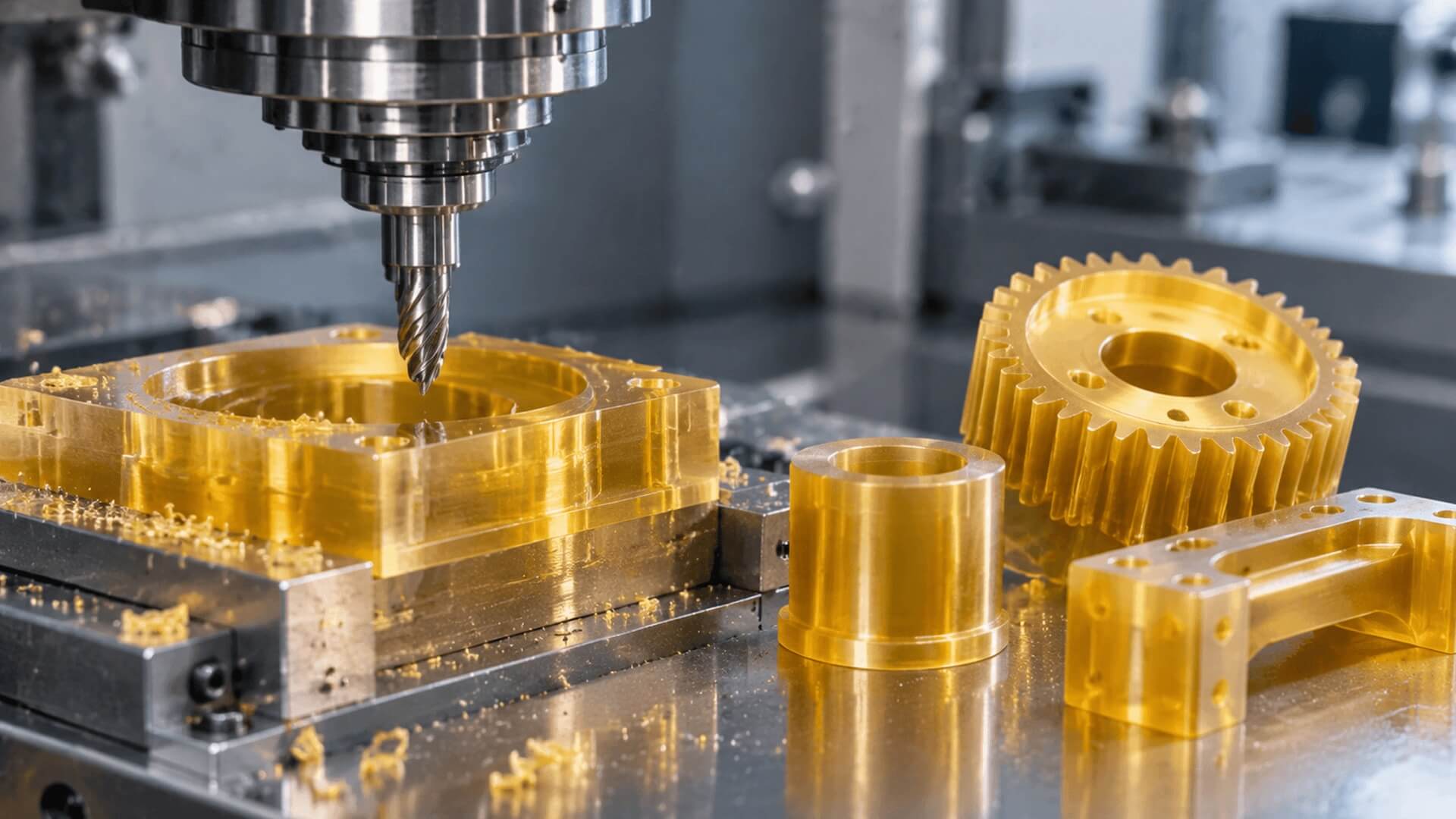
Polyetherimide (PEI), commercially known as Ultem, is an amorphous, amber-translucent high-performance thermoplastic engineered for demanding operating conditions where dimensional stability, dielectric strength, and broad chemical resistance must be maintained across extreme thermal spans. With an exceptionally high glass transition temperature (Tg=217°C/423°F) and continuous service capability up to 170°C (338°F), Ultem outperforms standard engineering polymers like polyacetal (POM), polyamide (Nylon), and polycarbonate (PC). It delivers a tensile modulus exceeding 3,200 MPa, inherent flame retardancy (UL94 V-0 at 0.4 mm thickness with minimal smoke emission), and compatibility with repeated autoclaving, gamma radiation, and ethylene oxide (EtO) sterilization.
However, subtractive manufacturing of Ultem presents distinct failure modes that trip up shops accustomed to cutting metals or semi-crystalline polymers like PEEK.
Because Ultem is completely amorphous—lacking the regular, crystal-matrix folding of PEEK or POM—its mechanical performance is dominated by high notch sensitivity, low elongation at break (under yield: 6% to 8%), and an extremely low thermal conductivity of approximately 0.22 W/(m⋅K).
During CNC milling and turning, mechanical shear energy cannot conduct away through the polymer core. The heat accumulates rapidly at the tool-chip interface.
If cutting parameters create excessive rubbing or localized tool deflection, high tensile residual stress gradients lock into the machined boundary layers. Days or weeks after shipment, parts that passed visual inspection can spontaneously fracture, craze, or shatter when exposed to internal assembly stresses or trace chemical cleaning agents.
Navigating these failure modes requires strict discipline across toolpath kinematics, multi-stage stress-relief annealing, coolant chemistry, and micro-machining parameters. Hardware engineering teams looking for certified aerospace, semiconductor, or medical components can partner with Celerity Precision through our custom plastic CNC machining services.
Table of Contents
The Primary Hazard: Environmental Stress Cracking (ESC) Mechanics
The most severe operational risk in precision Ultem machining is Environmental Stress Cracking (ESC). ESC accounts for over 85% of catastrophic field failures in machined PEI components.
Environmental Stress Cracking (ESC) Triad in Ultem (PEI)
Failure Mechanics AnalysisThe Physics of Stress Crazing
Amorphous thermoplastics consist of randomly entangled, high-molecular-weight polymer chains. When an end mill cuts Ultem with high tool pressure, a dull cutting edge, or excessive tool-shank rubbing, it stretches these polymer chains beyond their yield point, leaving high residual tensile stresses locked into the sub-surface layer (often exceeding 25 to 35 MPa).
When this stressed polymer contacts an incompatible chemical solvent, the solvent molecules diffuse into the inter-molecular spaces between the strained polymer chains.
The fluid acts as a localized plasticizer, lowering the cohesive energy required for chain disentanglement.
Microscopic crazes (networks of micro-voids interconnected by thin polymer fibrils) initiate at stress-concentration points. Under the sustained residual tensile stress from machining, these crazes rapidly rupture, transforming micro-cracks into through-body fractures without warning.
Chemical Incompatibility Blacklist
Ultem exhibits outstanding resistance to mineral acids, salt solutions, and alcohols, but it is vulnerable to polar organic solvents, ketones, and aromatic hydrocarbons.
The following substances must never contact Ultem components during machining, degreasing, ultrasonic cleaning, or post-processing inspection:
- Acetone, Methyl Ethyl Ketone (MEK), and Cyclohexanone (Initiate instantaneous catastrophic micro-cracking within seconds).
- Mineral Spirits, Kerosene, and Solvent-Based Degreasers.
- Chlorinated Hydrocarbons (Methylene Chloride, Trichloroethylene, Chloroform).
- Aromatic Hydrocarbons (Toluene, Xylene, Benzene).
- Ester-Based Synthetic Compressor Lubricants and Semi-Synthetic Cutting Oils containing chlorinated or sulfurized extreme-pressure (EP) additives.
To clean Ultem components, use only pure Isopropyl Alcohol (IPA) at concentrations under 70%, warm deionized water with mild, neutral-pH enzymatic detergents, or ultrasonic baths containing non-ionic surfactants, followed by an immediate pure deionized water rinse and controlled warm-air drying.
Recommended Speeds, Feeds & Cutting Parameters
Machining Ultem requires balancing linear cutting speed against mechanical chip load. If the tool spins too fast relative to the feed rate, the flutes burnish and rub against the polymer, creating localized frictional melting and high residual tensile stresses. If the feed rate is too aggressive without adequate edge sharpness, the high shear force chips the brittle material along exit edges.
The parameters below distinguish between unfilled Ultem 1000 and 30% glass-fiber-reinforced Ultem 2300:
- Ultem 1000 (Unfilled): Exhibits high ductility and optical clarity, but requires razor-sharp cutting edges to prevent gummy burrs, ribbon-chip wrap-around, and stress-cracking.
- Ultem 2300 (30% Glass-Filled): Multiplies tensile modulus (to 9,000 MPa) and halves the coefficient of linear thermal expansion, but the chopped, abrasive glass fibers cause rapid abrasive wear on standard carbide edges.
| Operation & Grade | Tooling Material / Coating | Speed (SFM) |
Speed (m/min) |
Chip Load / Feed (FPT / IPR) |
Radial (Ae) | Axial (Ap) |
|---|---|---|---|---|---|---|
| End Milling - Roughing PEI 1000 | Polished Micro-Grain Carbide | 350 – 600 | 105 – 180 | 0.06 – 0.12 mm/tooth | 0.30 – 0.50 × D | 0.75 – 1.25 × D |
| End Milling - Finishing PEI 1000 | Polished Micro-Grain Carbide | 500 – 800 | 150 – 245 | 0.02 – 0.05 mm/tooth | 0.05 – 0.10 × D | 0.25 – 0.75 × D |
| End Milling - Roughing GF30 | PCD or Diamond-Like Carbon (DLC) | 250 – 450 | 75 – 135 | 0.04 – 0.08 mm/tooth | 0.25 – 0.40 × D | 0.50 – 1.00 × D |
| End Milling - Finishing GF30 | Polycrystalline Diamond (PCD) | 400 – 650 | 120 – 200 | 0.02 – 0.04 mm/tooth | 0.04 – 0.08 × D | 0.20 – 0.50 × D |
| Turning - Roughing PEI 1000 | Uncoated Polished Carbide | 400 – 700 | 120 – 215 | 0.12 – 0.25 mm/rev | N/A | 1.50 – 3.00 mm |
| Turning - Finishing PEI 1000 | Uncoated Polished Carbide | 600 – 900 | 180 – 275 | 0.04 – 0.08 mm/rev | N/A | 0.25 – 0.60 mm |
| Turning - Roughing GF30 | PCD Insert (Fine Grain) | 300 – 500 | 90 – 150 | 0.08 – 0.18 mm/rev | N/A | 1.00 – 2.00 mm |
| Turning - Finishing GF30 | PCD Insert (Fine Grain) | 450 – 750 | 135 – 230 | 0.03 – 0.06 mm/rev | N/A | 0.20 – 0.40 mm |
| Deep-Hole Drilling PEI 1000 | Polished Parabolic Solid Carbide | 150 – 250 | 45 – 75 | 0.05 – 0.10 mm/rev | Full Drill D | 0.50 – 1.00 × D (Peck) |
| Deep-Hole Drilling GF30 | DLC Coated / Carbide Drill | 120 – 200 | 35 – 60 | 0.04 – 0.08 mm/rev | Full Drill D | 0.30 – 0.75 × D (Peck) |
Tooling Geometries & Coolant Protocols
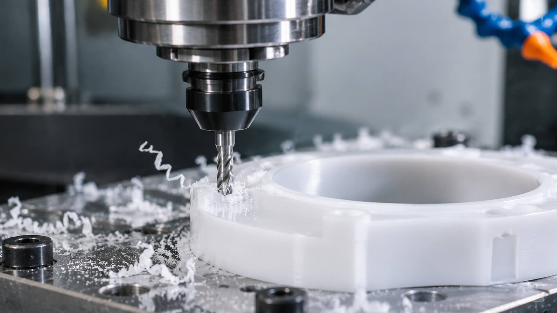
Cutting tools must slice cleanly through the polymer matrix with zero compressive burnishing. Standard metal-cutting end mills with negative rake angles, heavy corner hones, or protective chamfers compress Ultem elastically, trapping high frictional heat along the clearance land.
Carbide Tool Geometry for Ultem 1000
Unfilled PEI Micro-Geometry1. Tooling Substrates: Carbide vs. Polycrystalline Diamond (PCD)
- For Unfilled Ultem 1000: Use ultra-fine sub-micron grain solid carbide (WC-Co) with mirror-polished flutes (Ra<0.05μm). The tool must be uncoated or coated with thin, low-friction Diamond-Like Carbon (DLC). Thick physical vapor deposition (PVD) coatings (like TiAlN or AlCrN) round the cutting edge, increasing the cutting radius past 15 µm and driving up localized shear heat.
- For Glass-Filled Ultem 2300: Chopped glass fibers dull carbide cutting edges in minutes. Once a carbide tool loses its sharp edge, cutting forces rise, cracking the part. Tooling must use Polycrystalline Diamond (PCD) inserts or CVD diamond-coated end mills (film thickness 6–10 µm). PCD maintains an edge up to 30 times longer than standard carbide when milling 30% glass-filled polymer.
2. Cutter Geometries
- Rake Angles: Specify positive axial and radial rake angles between +10° and +15°. Positive rake angles shear the polymer chips smoothly upward along the flute, minimizing compressive stresses on the parent stock.
- Clearance and Relief Angles: Primary relief angles must be ground to +12° to +15°, with secondary relief between +18° and +22°. High clearance is essential to prevent the machined wall from snapping back against the tool clearance land.
- Flute Profiles: Use 2-flute end mills for slotting and pocket roughing to maximize chip evacuation space. 3-flute tools are acceptable for light side-finishing passes. Avoid 4-flute end mills; their small flute pockets trap continuous stringer chips, causing localized melting.
3. Drilling and Deep-Hole Protocols
Drilling generates more localized heat than any other subtractive operation on plastics. Standard 118° jobber drills pack chips down the hole, creating thermal melt rings, drill seizure, and catastrophic bore-wall cracking.
- Drill Geometry: Use parabolic-flute drills with a low helix angle (15° to 20°) to eject continuous chips up and out of the cut. The point angle should be 120° to 130°, with a thinned web to minimize center thrust.
- Kinematic Cycle: Program an aggressive full-retract peck drilling cycle (G83). Peck depths must not exceed 0.5×D to 1.0×D. The drill must fully retract outside the hole to clear continuous plastic ribbons and allow cooling air to flood the bore before re-entry.
4. Coolant Discipline: Cold Air Vortex vs. Specialized Synthetics
- Dry Machining with Cold-Air Vortex Guns (-10°C to 0°C): This is the benchmark method for medical, optical, and semiconductor components. High-pressure cold air chills the chip to reduce ductility, snaps continuous ribbons into manageable fragments, and blows chips out of the cutting zone without chemical contamination.
- Water-Miscible Synthetic Coolants: If liquid flood cooling is required for deep, complex pocketing, use exclusively oil-free, synthetic coolants formulated for engineering plastics. The emulsion must be completely free of mineral oils, sulfur, and chlorine. Maintain concentration between 5% and 7% in pure deionized water. Thoroughly rinse the finished components in deionized water immediately after machining.
The 3-Stage Ultem Annealing Process
Even with sharp tools and cold air cooling, machining removes material that releases internal stress gradients from extrusion or molding, shifting dimensions over time. Machining also introduces localized shear stresses along finish passes.
To prevent environmental stress cracking and achieve dimensional tolerances under ±0.010 mm, implement this 3-Stage Stress-Relief Annealing Process:
3-Stage Ultem (PEI) Annealing Thermal Profile
Stress-Relief Protocol- Pre-Machining Annealing: Relieves bulk internal stresses locked in during stock extrusion or plate pressing, minimizing warping during initial roughing.
- Intermediate Annealing: Applied after rough machining (leaving 0.50 mm to 0.75 mm of finish stock). This balances residual stresses across asymmetric features before finish cuts.
- Post-Machining Annealing: Stabilizes the finished crystalline-amorphous boundary layer after final profiling, ensuring resistance to ESC during service.
| Annealing Stage | Temperature Ramp-Up Rate | Soak / Dwell Temperature | Soak Duration (Wall Section) | Controlled Cooling Rate |
|---|---|---|---|---|
| Stage 1: Pre-Machining | +15°C / hr up to 140°C; then +10°C / hr to 205°C | 200°C – 205°C (392°F – 401°F) | 1 hour per 6 mm (0.25") of maximum cross-sectional thickness | -10°C / hr down to 140°C; then power-off oven cool down to < 50°C |
| Stage 2: Intermediate (Post-Roughing) |
+15°C / hr | 195°C – 200°C (383°F – 392°F) | 1 hour per 8 mm (0.31") of semi-machined wall section | -10°C / hr continuous down to 120°C; slow natural cool to room temp |
| Stage 3: Post-Machining (Final Stabilization) |
+10°C / hr | 185°C – 190°C (365°F – 374°F) | 2 to 4 hours static dwell time | -8°C / hr down to 40°C (Do NOT crack oven open prematurely) |
Critical Annealing Rule: Never open the annealing oven door prematurely. Exposing parts at 180°C to ambient air drafts produces thermal shock. The outer skin contracts rapidly around the warm core, creating severe surface tensile stresses that guarantee crazing. The oven must remain closed until the interior drops below 50°C (122°F).
High-Speed Kinematics & 5-Axis Machine Tool Integration
Ultem’s high notch sensitivity and low thermal conductivity require rigid machine setups. Any structural vibration or spindle runout over 0.005 mm acts as a hammer against the cutting zone, micro-fracturing the brittle plastic edges.
At Celerity Precision, we route complex Ultem components across specialized machine platforms:
1. Ultra-High-Speed Micro-Milling (Beijing Jingdiao JDGR200T)
Machining micro-fluidic channels, semiconductor test sockets, and thin-walled electrical housings requires high spindle speeds combined with light, precise chip loads to avoid burring:
- High-Frequency Direct-Drive Spindles: Our Beijing Jingdiao JDGR200T machining centers feature continuous 24,000 RPM high-speed spindles with dynamic runout under 0.001 mm (0.00004″).
- Burr-Free Micro-Tooling: Operating at 24,000 RPM allows tools as small as 0.20 mm to maintain proper surface speeds (SFM). The cutter slices cleanly through Ultem fibers without heat accumulation, producing optical-grade surface finishes (Ra≤0.2μm) and burr-free edges without requiring manual deburring.
2. Single-Setup Complex 5-Axis Machining (Hermle C400)
Complex aerospace fuel-system manifolds, surgical instrument handles, and downhole electrical chassis often require multi-side machining:
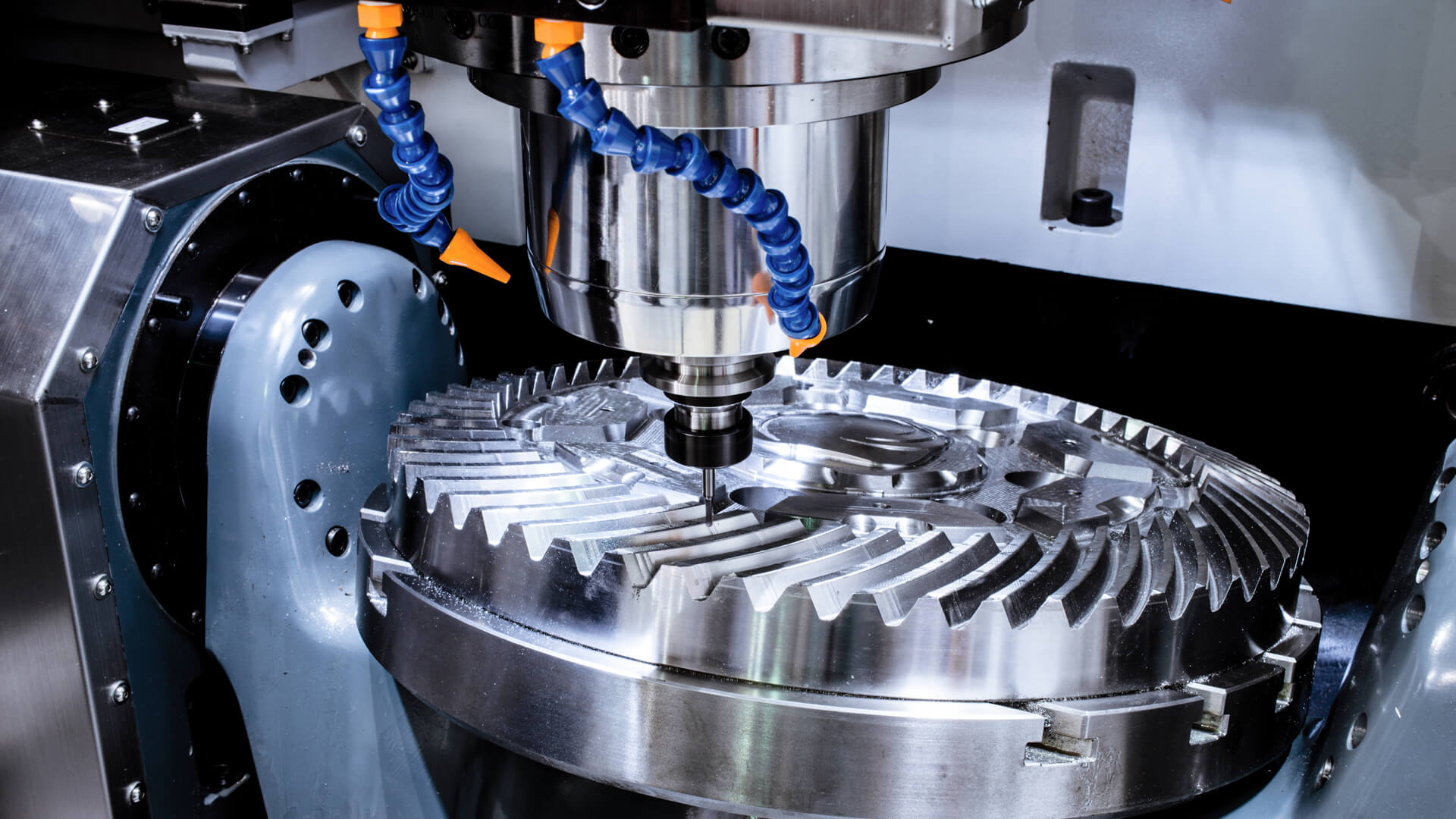
- Eliminating Multi-Clamping Stresses: Clamping a flexible polymer in multiple vises introduces cumulative clamping stresses. On our German Hermle C400 5-axis CNC machining centers, multi-sided parts are machined in a single clamping setup.
- Mineral-Cast Polymer Concrete Damping: The Hermle C400 utilizes a mineral-cast base with dynamic structural vibration damping up to 10 times higher than welded steel. This damping eliminates regenerative chatter during dynamic trochoidal roughing, preventing micro-stress fractures in Ultem parts.
To explore our full production infrastructure, review our precision CNC milling capabilities.
Quality Verification: Polarized Light Analysis & Zeiss CMM Metrology
Validating precision Ultem components requires metrology workflows tailored to polymer physics:
1. Photoelastic Polarized Light Stress Inspection
Because unfilled Ultem 1000 is naturally amber-translucent, it exhibits photoelastic birefringence under cross-polarized light. When polarized light passes through stressed amorphous polymer chains, the refraction index splits relative to principal stress directions, creating colored interference fringes (isochromatic fringes).
Photoelastic Polariscopic Stress Verification Protocol
Non-Destructive Optical QAAt Celerity Precision, critical Ultem 1000 parts are evaluated under an optical polariscope before and after finish annealing:
- Passing Standard: The part displays uniform, uninterrupted amber light transmission across cross-sections, with no localized rainbow-ring concentrations.
- Failing Standard: Clustered, tightly spaced rainbow fringes around bolt holes, sharp internal corners, or pockets reveal dangerous residual tensile stresses. These parts are routed back for intermediate annealing before finish cutting.
2. Zeiss CMM Dimensional Inspection
Spatial dimensional verification is conducted in our climate-controlled quality assurance laboratory, maintained at 20°C ± 1°C (68°F ± 1.8°F).
- Thermal Equilibration: Before inspection, parts rest inside the metrology lab for 4 to 8 hours to reach thermal equilibrium, preventing errors from the material’s thermal expansion (CLTE≈56×10⁻⁶/K for Ultem 1000).
- Low-Force Zeiss Scanning Probes: Probing is performed on our bridge-type Zeiss CMM. Scanning speeds and trigger forces are dialed in to prevent probe stylus tips from deflecting thin walls or indenting soft polymer faces, verifying hole diameters and true positions down to ±0.005 mm (±0.0002″).
- Non-Contact Video Metrology: Thin-walled housings vulnerable to contact deflection are verified using automated high-resolution optical video measurement systems.
3. Material Lot Authentication via XRF Analysis
A growing issue in precision polymer supply chains is the blending of recycled regrind scrap or uncertified generic PEI resins into virgin billets. Regrind resins degrade tensile strength, lower dielectric resistance, and increase ESC susceptibility.
Celerity Precision verifies incoming raw bar stock, sheet, and extruded blanks using an on-site X-Ray Fluorescence (XRF) Spectrometer / Analyzer:
- Lot-Level Screening: Every material lot is screened for trace heavy-metal contamination, non-compliant halogenated flame retardants, and unauthorized mineral fillers.
- Material Pedigree Traceability: Spectroscopic lot signatures are verified directly against raw resin Mill Test Reports (MTRs), certifying that medical and aerospace orders run on 100% prime virgin resin.
DFM Rules to Prevent In-Service Stress Cracking
Applying disciplined Design for Manufacturability (DFM) principles during CAD modeling reduces machining hours, limits scrap rates, and ensures long service life for Ultem parts:
1. Maintain Internal Corner Radii (R ≥ 1.0 mm)
Ultem is notch sensitive. Designing sharp internal 90° corners (R<0.5 mm) creates severe stress-concentration points where micro-cracks readily propagate.
- DFM Rule: Design all internal corner radii to at least R≥1.00 mm (0.040″), and ideally R≥1.50 mm. Radiused corners reduce local stress-concentration factors (Kₜ) by more than 60%, while allowing CNC machinists to use rigid, larger-diameter end mills that clear material without tool deflection. Kt
2. Use Threaded Inserts Instead of Direct Tapping
Tapping fine-pitch machine threads (smaller than M4 or #8-32) directly into Ultem creates sharp, notch-sensitive thread roots. When mating screws are torqued down, hoop stresses combine with notch sensitivity to shear the polymer threads or crack the surrounding boss.
- DFM Rule: For assemblies requiring repeated field disassembly or high clamp loads, design holes for press-fit or heat-staked threaded brass/stainless steel inserts (such as Helicoil or Dodge ultrasonic inserts). If direct threads are necessary, use coarse, rounded thread profiles (such as unified coarse UNC or stub acme profiles), and ensure the thread engagement depth does not exceed 1.5×D.
3. Maintain Consistent Wall Thicknesses
Asymmetric geometry with sudden cross-sectional transitions (such as a 6 mm floor meeting an unsupported 0.8 mm wall) generates internal differential stress during annealing cycles, causing dimensional warping.
- DFM Rule: Design uniform wall thicknesses between 1.50 mm and 3.50 mm across the component. When transitions are necessary, use gradual blend tapers (minimum 3:1 ramp slope) and generous transition fillets to distribute cooling stresses evenly across the part.
4. Limit Deep Blind-Hole Aspect Ratios
Deep, narrow blind holes trap heat and continuous chips, melting the hole bottom and causing circumferential stress cracking.
- DFM Rule: Limit blind hole depths to ≤3× hole diameter. When deeper blind holes are required, specify step-drilled diameters or add a through-port relief hole at the bottom to allow cold-air evacuation and chip clearing.
Precision Ultem Manufacturing for Critical Hardware
Machining Ultem (PEI 1000 and Ultem 2300) without distortion or premature field cracking requires balancing polymer thermodynamics, dedicated high-speed machine tools, multi-stage annealing cycles, and polarized light stress verification.
Whether your program requires complex micro-fluidic manifolds milled on our 5-axis CNC machining centers or production runs of tight-tolerance electrical connectors supported by our custom plastic CNC machining services, Celerity Precision delivers repeatable components backed by comprehensive Zeiss CMM inspection reports.
Request an Engineering DFM Review and Precision Ultem Quote
Send your 3D CAD models (STEP, IGS) and 2D engineering drawings to our plastics application engineering team. We will deliver a complimentary, comprehensive DFM review within 24 hours, evaluating wall transitions, stress-relief allowances, tooling paths, and transparent factory-direct pricing.
- Strict Non-Disclosure Agreement (NDA) Protection
- 24-Hour Engineering DFM & Quotation Turnaround
- Polarized Light Stress Inspection & Zeiss CMM Dimensional Certification
Upload your CAD drawings via our contact page to begin your project review with our engineering team.

CP Engineering Team
Authored and peer-reviewed by the Senior Engineering and Metrology Team at Celerity Precision. Backed by German 5-axis CNC machining centers, high-speed micro-milling platforms, and a climate-controlled Zeiss CMM inspection lab, our team delivers deep DFM insights, material machinability guides, and precision manufacturing solutions for aerospace, medical, and semiconductor developers worldwide.