Machining Teflon (PTFE): Turning, Milling, Cold Flow Prevention & Tight Tolerance Control

Polytetrafluoroethylene (PTFE), universally recognized under the DuPont trade name Teflon, is a fluoropolymer with distinct engineering characteristics. Consisting of a linear carbon-carbon backbone enveloped by an electro-negative sheath of fluorine atoms ([−CF₂-CF₂−]ₙ), PTFE possesses the lowest dynamic coefficient of friction of any solid engineering material (μ≈0.04 to 0.10 against polished steel).
Coupled with a continuous service temperature span from cryogenic extremes (-200°C / -328°F) up to +260°C (+500°F), total chemical inertness to aggressive acids, bases, and organic solvents, and zero water absorption (<0.01%), PTFE is an essential material for high-purity semiconductor chemical delivery, aerospace cryogenic seals, analytical laboratory valves, and pharmaceutical diaphragm pumps.
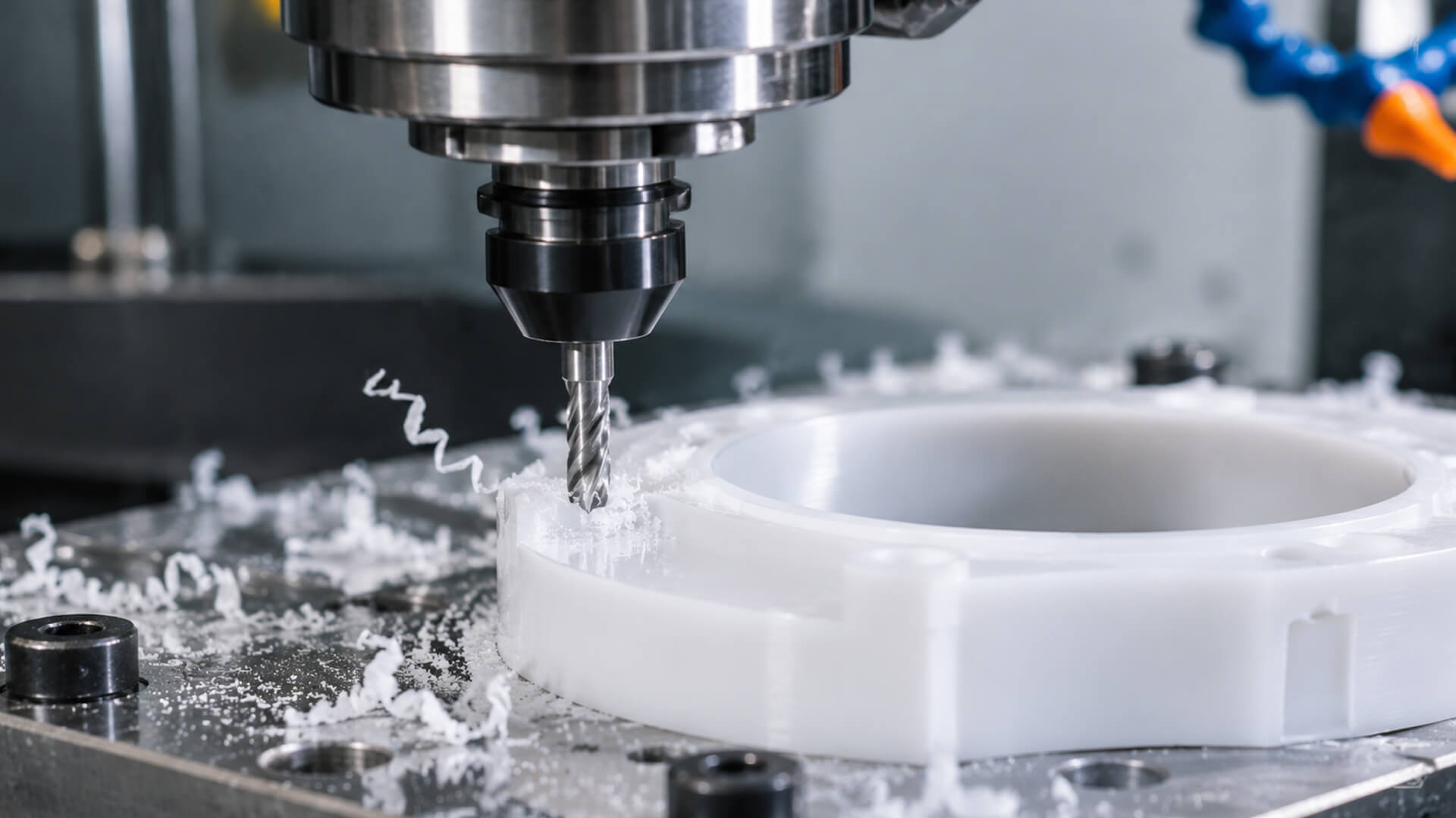
However, from the perspective of subtractive CNC manufacturing, PTFE is notoriously difficult to machine to tight tolerances.
Unlike rigid engineering thermoplastics such as PEEK, Ultem, or Delrin, PTFE behaves as a non-rigid, highly viscoelastic polymer. It possesses an exceptionally low modulus of elasticity (E≈400 to 750 MPa, less than one-fifth that of Delrin and roughly 0.6% that of 6061-T6 aluminum).
Under cutting forces, the material deforms elastically away from the tool and springs back after the cut, creating dimensional taper and out-of-round features.
Furthermore, PTFE exhibits three severe physical failure modes:
- High Cold-Flow Creep: Under relatively modest mechanical loads (even static vise clamping pressures exceeding 3 to 5 MPa), PTFE experiences continuous, time-dependent plastic deformation at room temperature.
- High Linear Thermal Expansion: Possessing a Coefficient of Linear Thermal Expansion (CLTE) of 120 to160×10⁻⁶/K —more than seven times that of carbon steel—modest ambient temperature fluctuations cause significant dimensional drift.
- Severe Edge Burring: High tensile elongation (200% to 400% before fracture) prevents chips from snapping cleanly, producing stubborn, fibrous stringer burrs along every tool exit plane.
Navigating these challenges requires specialized razor-blade cutting geometries, non-distorting workholding fixtures, structured thermal stabilization, and non-contact optical metrology. Hardware engineering teams developing mission-critical fluoropolymer assemblies can partner with Celerity Precision through our custom PTFE Teflon CNC machining services.
Table of Contents
The 19°C Phase Transition Anomaly & Thermal Stability
The primary cause of dimensional non-conformance in precision-machined PTFE is the 19°C (66°F) Crystalline Phase Transition Anomaly.
Most machine shops operate under standard commercial HVAC conditions where seasonal shop-floor temperatures swing between 16°C (61°F) in winter and 26°C (79°F) in summer. In standard metals or amorphous plastics, this 10°C delta produces minor thermal expansion. In PTFE, crossing 19°C triggers a physical change in crystallographic structure.
Crystallographic Phase Transition in PTFE at 19°C
Crystalline Inversion AnomalyBelow 19°C (66°F)
Phase II • Cold StateAbove 19°C (66°F)
Phase IV • ExpandedBelow 19°C, PTFE exists in its Phase II crystalline state, characterized by a dense, well-ordered triclinic crystal lattice where the polymer chain forms a tight helix with 13 CF₂ groups per 180° twist.
As the material warms through 19°C, the molecular helix untwists to 15 CF₂ groups per turn, transforming into the Phase IV hexagonal crystalline structure.
This uncoiling triggers a sharp, step-function volumetric expansion of 1.0% to 1.2%, producing an immediate linear dimensional increase of approximately 0.3% to 0.4%.
For a 50.00 mm diameter seal, crossing this 19°C threshold causes an abrupt dimensional jump of 0.150 mm to 0.200 mm (0.006″ to 0.008″)—completely outstripping standard drawing tolerances.
The Thermal Normalization Mandate (20°C ± 1°C)
Because of this phase transition anomaly, precision PTFE machining and metrology cannot be conducted in variable ambient environments:
- Strict 20°C Climate-Controlled Production: At Celerity Precision, raw PTFE stock, CNC machine tool enclosures, and metrology labs are maintained at a continuous 0°C ± 1°C (68°F ± 1.8°F). Machining and probing are deliberately stabilized above the 19°C transition point, holding the crystal lattice in its stable hexagonal phase throughout processing.
- Raw Material Thermal Soaking: Raw extruded rods and compression-molded billets must soak inside our climate-controlled cell for a minimum of 4 hours prior to clamping to ensure that core temperatures normalize to 20°C. Machining a cold billet straight from an unheated warehouse guarantees parts will swell out of spec within hours.
Material Grade Selection: Virgin vs. Filled PTFE Formulations
To overcome virgin PTFE’s susceptibility to cold-flow creep, wear, and thermal expansion, material compounders blend inorganic micro-fillers into the matrix. Selecting the correct formulation dictates cutting tool substrates, surface finishes, and speeds and feeds:
1. Virgin PTFE (Unfilled / Medical Grade)
Virgin PTFE is an unpigmented, pure white fluoropolymer offering the highest chemical purity, lowest friction coefficient, superior dielectric strength, and FDA/USP Class VI biocompatibility.
However, it exhibits low compressive creep resistance under continuous load.
It is specified for ultra-pure semiconductor fluid manifolds, pharmaceutical valve diaphragms, high-voltage insulators, and low-friction bearings.
From a machining standpoint, virgin PTFE is soft and elastic, requiring razor-sharp cutting edges to prevent gummy burrs, localized tearing, and tool push-off.
2. 15% to 25% Glass-Filled PTFE
Compounding 15% to 25% chopped E-glass micro-fibers into the resin decreases compressive cold-flow creep by up to 80%, doubles the flexural modulus, and cuts thermal expansion by approximately 40%.
It is widely specified for dynamic hydraulic piston rings, valve seats, and mechanical shaft packings.
However, the embedded glass fibers are extremely abrasive. Standard tungsten carbide cutting tools experience rapid flank wear within minutes, requiring Polycrystalline Diamond (PCD) tooling to maintain edge sharpness.
3. 25% Carbon-Filled PTFE
Blending 25% fine carbon powder into the fluoropolymer increases compressive strength, surface hardness, and thermal conductivity by over 500% (∼1.0 W/(m⋅K) compared to 0.25 W/(m⋅K) for virgin PTFE).
It lowers electrical surface resistivity into the static-dissipative range (<10⁵Ω), making it ideal for ATEX-rated fuel-system slide rings, rotary air-compressor seals, and water-lubricated bearings.
Carbon-filled PTFE produces fine, discontinuous chips during turning, but the carbon particles require specialized chip extraction and vacuum setups to protect machine ways.
| Physical & Mechanical Property | Virgin PTFE Unfilled | 15% Glass PTFE Reinforced | 25% Carbon PTFE Static-Dissipative | Engineering & CNC Machining Impact |
|---|---|---|---|---|
| Tensile Strength at Break | 25 – 35 MPa (3.6–5.1 KSI) | 15 – 22 MPa (2.2–3.2 KSI) | 12 – 18 MPa (1.7–2.6 KSI) | Virgin PTFE offers extreme tensile ductility (elongation up to 400%); filled grades shear cleanly. |
| Modulus of Elasticity (Tensile) | 400 – 650 MPa (Extremely Flexible) | 800 – 1,200 MPa | 1,000 – 1,500 MPa (Stiffest) | Critical: Virgin PTFE deflects elastically under cutter side-pressure; requires razor tools and light finish cuts. |
| Hardness (Shore D) | 50 – 55 Shore D | 58 – 62 Shore D | 62 – 68 Shore D | Virgin PTFE is vulnerable to mechanical vise jaw indentation and clamping crush. |
| Coefficient of Linear Thermal Expansion | 130 – 160 × 10⁻⁶ / K | 85 – 105 × 10⁻⁶ / K | 65 – 85 × 10⁻⁶ / K (-50% Drift) | Carbon-filled cuts thermal drift in half; virgin expands rapidly under spindle heat. |
| Deformation Under Load (14 MPa, 24h) | 12% – 16% (Severe Creep) | 3% – 5% (Resistant) | 2% – 4% (Maximum Rigidity) | Decision Gate: Inorganic fillers prevent long-term compressive creep and seal bolt-load relaxation. |
| Relative Abrasiveness to Tooling | Low (Zero filler wear) | Severe (Rapid Flank Wear) | Moderate to High | Glass-filled requires PCD diamond tooling; virgin requires polished sharp uncoated carbide. |
| Primary Industrial Applications | Semiconductor Valves, Pure Seals | High-Pressure Hydraulic Packings | Compressor Vanes, ATEX Seals | Formulations match distinct chemical, electrical, and mechanical environments. |
Speeds, Feeds & Cutting Parameters
Machining PTFE successfully relies on a specific mechanical strategy: high surface speeds combined with light-to-moderate feed rates and shallow depths of cut.
Because the polymer’s thermal conductivity is low (0.25 W/(m⋅K)), cutting heat does not conduct into the chip or the parent stock. The heat remains concentrated at the cutting edge.
If cutting parameters allow the tool to dwell, rub, or plunge with excessive feed, the material heats locally, expands, smears, and produces heavy, fibrous burrs along every corner.
Conversely, taking excessively heavy roughing cuts in virgin PTFE causes the flexible stock to deflect elastically around the tool (tool push-off). The cutter pushes the material aside rather than cleanly shearing it, producing tapered bores and bulging diameters.
| Operation & Grade | Tooling Substrate / Coating | Speed (SFM) |
Speed (m/min) |
Chip Load / Feed (FPT / IPR) |
Radial (Ae) | Axial (Ap) |
|---|---|---|---|---|---|---|
| Precision Turning - Roughing Virgin | Uncoated Polished Carbide | 600 – 1,200 | 180 – 365 | 0.12 – 0.25 mm/rev | N/A | 1.00 – 3.00 mm |
| Precision Turning - Finishing Virgin | Razor Polished Carbide (0.2mm R) | 800 – 1,600 | 240 – 485 | 0.04 – 0.10 mm/rev | N/A | 0.20 – 0.50 mm |
| Precision Turning - Roughing Filled PCD | Polycrystalline Diamond (PCD) | 400 – 800 | 120 – 240 | 0.08 – 0.18 mm/rev | N/A | 0.75 – 2.00 mm |
| Precision Turning - Finishing Filled PCD | Fine-Grain PCD (0.2mm Nose R) | 600 – 1,200 | 180 – 365 | 0.03 – 0.08 mm/rev | N/A | 0.15 – 0.40 mm |
| High-Speed End Milling Virgin | Polished Solid Carbide (1-2 Flute) | 800 – 1,800 | 240 – 550 | 0.08 – 0.15 mm/tooth | 0.30 – 0.50 × D | 0.75 – 1.50 × D |
| End Milling - Finishing Single Flute | Polished Carbide (Single Flute) | 1,200 – 2,400 | 365 – 730 | 0.02 – 0.06 mm/tooth | 0.05 – 0.10 × D | 0.25 – 0.75 × D |
| High-Speed End Milling Filled PCD | PCD Tipped / CVD Diamond Mill | 500 – 1,000 | 150 – 300 | 0.04 – 0.10 mm/tooth | 0.20 – 0.40 × D | 0.50 – 1.00 × D |
| End Milling - Finishing Filled PCD | Fine-Grain PCD End Mill | 800 – 1,500 | 240 – 450 | 0.02 – 0.05 mm/tooth | 0.04 – 0.08 × D | 0.20 – 0.50 × D |
| Standard Twist Drilling Virgin | Polished High-Helix Solid Carbide | 250 – 500 | 75 – 150 | 0.08 – 0.20 mm/rev | Full Drill D | 1.00 – 2.00 × D (Peck) |
| Deep-Hole Drilling (>3D) Virgin | Parabolic Flute Carbide Drill | 200 – 400 | 60 – 120 | 0.05 – 0.12 mm/rev | Full Drill D | 0.50 – 1.00 × D (Peck) |
| Drilling / Boring Filled PCD | Diamond-Coated / PCD Boring Bar | 150 – 350 | 45 – 105 | 0.04 – 0.10 mm/rev | Full Drill D | 0.50 – 1.00 × D (Peck) |
Tooling Geometry: The "Razor-Blade" Cutting Principle
Standard cutting tools engineered for metals or structural plastics fail in PTFE machining.
Steel and aluminum cutters utilize neutral or moderate positive rake angles (+5° to +10°) and feature micro-honed edge radii (rβ=10 to 25 μm) to resist mechanical chipping under heavy shear forces.
In soft, viscoelastic PTFE, these rounded cutting edges act as a wedge, plowing, compressing, and pushing material rather than shearing it cleanly.
Comparative Cutting Wedge Mechanics in PTFE
Tool-Workpiece KinematicsStandard Metal-Cutting Tooling
Compressive PlowingRazor-Sharp PTFE Tooling
Zero-Stress Shearing. The Razor-Blade Geometry Rules
- Razor-Sharp Edge Radii (rβ<2 to 3μm): Tooling must be ground to a dead-sharp cutting edge with zero honing. Uncoated, sub-micron grain solid carbide ground with ultra-fine diamond wheels achieves an edge sharpness that slices through ductile polymer chains without elastic deflection.
- High Positive Rake Angles (+20° to +30°): An aggressive positive rake angle lifts chips cleanly off the parent stock with minimal cutting resistance, reducing normal forces that cause tool push-off.
- Generous Primary and Secondary Clearance Angles (+10° to +15°): Because PTFE springs back elastically after shearing, standard small clearance angles allow the newly machined face to rub against the flank land of the tool. High relief angles eliminate this friction, preventing heat buildup and dimensional taper.
- Polished Flute Topography: Milling flutes and turning inserts must feature an optical mirror polish (Ra<0.05μm). The low surface energy of PTFE allows chips to slide smoothly up polished flutes without snagging or friction melting.
- Single-Flute End Mills for Milling: Use single-flute (O-flute) solid carbide router bits for slotting and pocketing virgin PTFE. Single-flute geometry provides the largest possible chip evacuation valley, preventing continuous ribbon chips from packing inside the flutes.
2. Tooling Materials: Carbide vs. Polycrystalline Diamond (PCD)
- For Virgin PTFE: Use ultra-fine sub-micron grain solid tungsten carbide left completely uncoated. Physical vapor deposition (PVD) coatings (like TiAlN or AlCrN) are counterproductive; the coating deposition process blunts the razor cutting edge, increasing the edge radius to over 10 µm. Uncoated polished carbide retains the sharpest possible shearing edge.
- For Glass-Filled and Carbon-Filled PTFE: The abrasive chopped glass and carbon fibers will wear a carbide cutting edge within minutes. Once carbide loses its edge, cutting forces rise and parts warp. For filled grades, Polycrystalline Diamond (PCD) tooling is mandatory. Fine-grained PCD (2 µm diamond grain size) maintains a razor-sharp cutting edge up to 50 times longer than solid carbide, holding critical bore tolerances under ±0.005 mm across production batches.
Anti-Deformation Workholding Tactics
More PTFE parts are scrapped during the workholding setup than during actual spindle cutting.
Due to its low elastic modulus (E≈500 MPa) and high creep under load, clamping a PTFE component in standard machine vises or 3-jaw chucks with serrated steel jaws produces permanent compressive indentation and geometric distortion.
Vise Clamping Elastic-Plastic Deformation Trap
Workholding & Creep DefectAt Celerity Precision, we implement three specialized anti-deformation fixturing strategies:
1. 360° Wrap-Around Contoured Soft Jaws (Pie Jaws)
When turning precision PTFE rings, seals, and bushings on CNC lathes, standard 3-point hard jaws concentrate clamping forces at three narrow contact points, crushing the cylinder into a triangular or oval shape.
- The Solution: Machine full-contact, 360-degree wrap-around aluminum pie jaws or machinable plastic soft jaws that match the exact outer diameter of the workpiece.
- Pneumatic Low-Pressure Clamping: Lathe chuck hydraulic systems must be fitted with precision pressure regulators dialed down to less than 0.5 to 1.0 bar (7 to 15 PSI). Wrapping clamping force evenly across 100% of the circumferential surface area allows the part to be held securely without plastic crushing.
2. Expanding Internal Mandrels for Thin-Walled Sleeves
Turning thin-walled PTFE sleeves and dynamic lip seals (<1.5 mm wall thickness) is challenging because exterior chuck clamping collapses the sleeve, while internal boring tools cause the flexible wall to chatter and push away.
- The Solution: Mount the pre-turned tube blank onto a custom-ground expanding internal aluminum mandrel. The mandrel supports the inside diameter along its full length with uniform radial pressure, providing the rigidity needed to turn tight-tolerance exterior diameters, grooves, and seal profiles without chatter or ovality.
3. Porous Ceramic Vacuum Chucks for Flat Sheet Milling
Milling thin PTFE diaphragm plates, gaskets, and semiconductor manifold plates in mechanical vises is impractical; edge clamping forces buckle the sheet upward in the center.
- The Solution: Secure flat stock using porous ceramic vacuum chucks. Atmospheric pressure applies an even, downward clamping force (∼1 bar/14.7 PSI) across the entire bottom surface of the sheet. Vacuum workholding completely eliminates mechanical stress concentrations, keeping flat plates true, flat, and parallel without surface marks.
For micro-machined parts with through-cutout geometries, supplement vacuum clamping with specialized water-soluble adhesive films or low-temperature thermo-release holding wax.
Coolant Protocols & Burr Removal Strategies
Thermal management during cutting is essential to prevent localized expansion and gummy burr formation, but coolant chemistry must match component end-use requirements:
Cooling Strategy Selection for PTFE Machining
Application-Specific ProtocolSemiconductor & Medical
Cleanroom GradeIndustrial & Automotive Seals
High-Rate Turning- Vortex Cold-Air Guns (-10°C to 0°C): This is the benchmark cooling method for semiconductor fluid components and cleanroom medical parts. Pressurized dry air passed through a vortex tube drops to sub-zero temperatures.
Directed at the tool-chip interface, this cold air stream cools the localized shear zone, increases the instantaneous flexural modulus of the ductile chip (making it stiffer and easier to shear cleanly), and blows continuous ribbons out of the cut without chemical contamination.
- Water-Soluble Synthetic Coolants: For production turning of industrial seals and deep-hole drilling where fluid lubrication is necessary to prevent chip packing, use oil-free water-soluble synthetic emulsions mixed at 5% to 7% concentration.
Never use sulfurized or heavy mineral cutting oils; porous fluoropolymers can absorb trace hydrocarbons, leading to outgassing and fluid path contamination.
Burr Elimination Strategies
Because PTFE exhibits high tensile elongation (up to 400%), chips do not naturally shear off cleanly along edges. Instead, the material rolls over the edge, forming tough, fibrous burrs that resist manual deburring knives.
To eliminate burrs:
- Always Program Climb Milling (Down Milling): Conventional milling rolls material forward into a heavy exit burr. Climb milling ensures the tooth enters at maximum chip thickness and exits at zero thickness, minimizing edge breakout.
- Programmed Reversible Back-Chamfer Passes: Incorporate high-speed 45° chamfering toolpaths directly into the CNC program to cut off feather burrs before the part leaves the fixture.
- Cryogenic Tumble Deburring: For high-volume production of miniature PTFE seals and electrical insulators, route parts through a cryogenic tumbling chamber. Liquid nitrogen chills the components below their glass transition temperature (-110°C), making the thin surface burrs brittle. High-speed media tumbling then fractures the brittle burrs cleanly from the ductile core without affecting dimensional tolerances.
Shop-Floor Capabilities: Celerity’s Precision Centers
Machining soft, elastic fluoropolymers without distortion requires dynamic machine tools equipped with high-speed spindles and fine feed control.
At Celerity Precision, fluoropolymer components are routed across dedicated machining cells:
1. Ultra-High-Speed Micro-Milling (Beijing Jingdiao JDGR200T)
Semiconductor fluidic manifolds, micro-nozzle plates, and high-frequency RF dielectric insulators with fine-pitch channels and small radii:
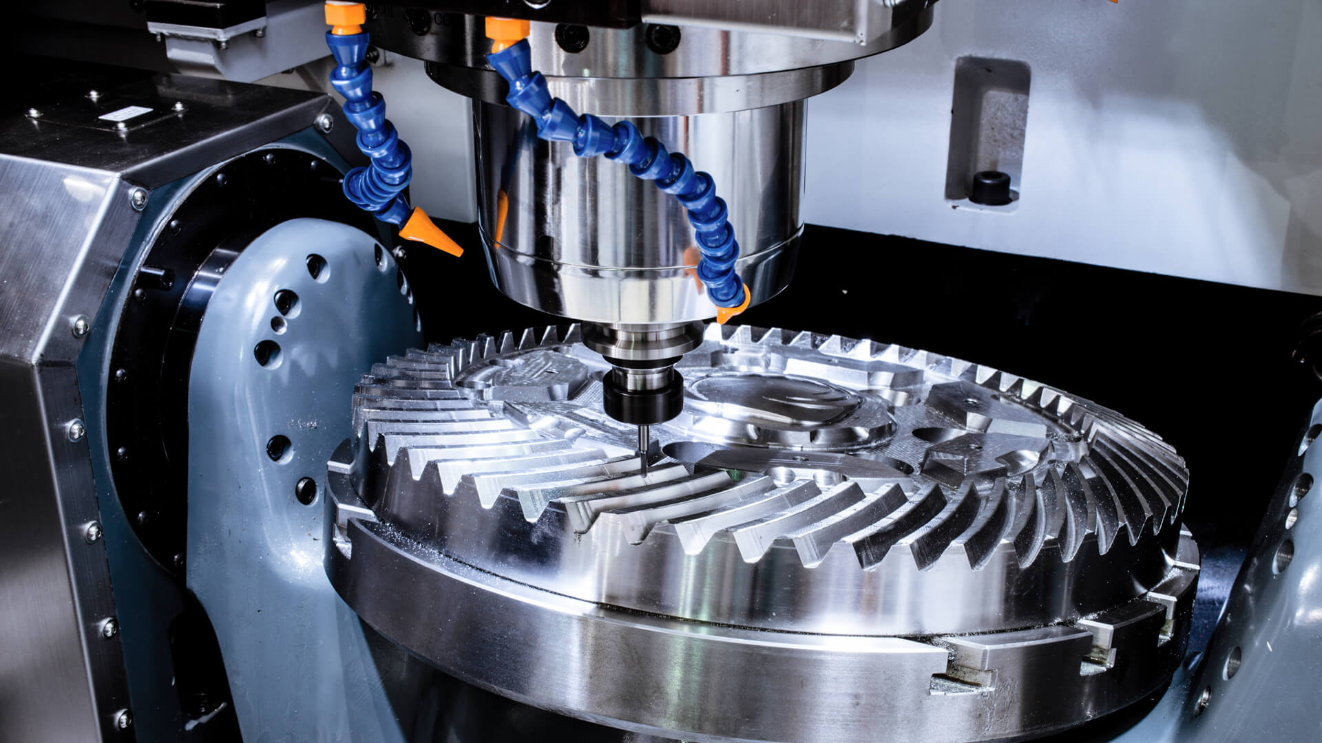
- 4,000 RPM High-Speed Electro-Spindles: Our Beijing Jingdiao JDGR200T 5-axis high-speed machining centers utilize direct-drive spindles with dynamic radial runout verified under .001 mm (0.00004″).
- High-Speed Shearing Kinematics: Operating at 24,000 RPM allows micro-end mills down to 0.20 mm diameter to maintain proper surface cutting speeds (SFM). High-speed shearing slices cleanly through ductile fluorocarbon chains without heat accumulation, producing burr-free edge transitions and mirror-like surface finishes (Ra≤0.2μm) without secondary bench polishing.
2. High-Speed Production Kinematics (Makino a40 & Precision Lathes)
For volume runs of precision valve bodies, cryogenic seals, and bearing bushings:
- Horizontal Chip Evacuation Stability: Our Makino a40 horizontal machining centers utilize rigid stepped-column castings. The horizontal spindle orientation allows continuous, ductile PTFE chip streams to drop away under gravity directly into the chip conveyor, preventing chip re-cutting and surface scratching.
- Precision CNC Turning with Low-Pressure Pneumatics: Our turning centers feature precision pneumatic chucking systems calibrated for sub-0.5 bar clamping, allowing us to turn thin-walled bushings down to ±0.005 mm (±0.0002″) without roundness distortion.
To review our complete production facilities, explore our precision CNC turning services and custom CNC milling capabilities.
Precision Metrology & Quality Assurance Standards
Verifying tight tolerances on soft, flexible PTFE components requires metrology workflows tailored to non-rigid materials:
Non-Contact Optical Metrology Pipeline
Sub-Pixel QA Architecture1. Non-Contact Optical Metrology via Vision Measuring Machines (VMM)
The primary inspection trap with PTFE is using standard contact metrology tools (such as manual micrometers, vernier calipers, or dial bore gauges).
Because PTFE has an elastic modulus under 700 MPa, the mechanical contact force of a micrometer anvil easily compresses the soft polymer face by 0.02 mm to 0.05 mm, generating false undersized readings.
- Automatic Image Measuring Instrument: Celerity Precision inspects delicate PTFE seals, thin-walled diaphragm rims, and fluidic O-ring grooves using automated Vision Measuring Machines (VMM).
- Telecentric Optical Profiling: Multi-angle programmable LED ring illumination and high-resolution telecentric optical lenses capture part geometries without physical contact. The automated system measures diameters, edge radii, and pitch centerlines down to ±0.002 mm (±0.00008″) without contact deflection errors.
2. Zeiss CMM Ultra-Low Force Contact Scanning
For complex 3D semiconductor valve manifolds with internal intersecting cross-ports where optical line-of-sight is blocked:
- Climate-Controlled Metrology: All components soak inside our dedicated quality assurance laboratory at 0°C ± 1°C (68°F ± 1.8°F) for a minimum of 8 to 12 hours prior to measurement, stabilizing the material above the 19°C phase transition threshold.
- Ultra-Low Force Probe Calibration: Three-dimensional spatial geometries and GD&T position tolerances are verified on our bridge-type Zeiss CMM. Contact scanning probes are configured with specialized micro-stylus systems calibrated to an ultra-low contact trigger force under .03 N (3 grams). This light touch prevents the stylus tip from indenting or dragging across the soft fluoropolymer face, ensuring verified spatial measurements down to ±0.005 mm (±0.0002″).
3. Raw Material Authentication: Density Verification & XRF Screening
Because raw PTFE resin cannot be melted and injection molded (it must be compression-molded and sintered like powdered metal), low-cost suppliers sometimes blend uncertified recycled scrap or regrind scrap into billets. Recycled PTFE lowers tensile elongation, increases microporosity, and causes localized leaks under high-vacuum service.
Celerity Precision verifies incoming raw rods, compression-molded billets, and extruded sheets through a two-stage quality protocol:
- Specific Gravity Density Verification: Density is verified via immersion displacement metrology against ASTM D792 standards:
- Virgin Unfilled PTFE: Confirms density between .14 and 2.18 g/cm³. Lower density indicates under-sintered porous material or recycled regrind contamination.
- 15%–25% Glass-Filled PTFE: Confirms density between .20 and 2.25 g/cm³.
- 5% Carbon-Filled PTFE: Confirms density between .05 and 2.12 g/cm³.
- XRF Elemental Verification: Material lots undergo non-destructive inspection using an on-site X-Ray Fluorescence (XRF) Spectrometer / Analyzer to confirm the absence of heavy-metal contaminants and verify exact elemental glass and mineral filler percentages. All components ship with full material certification records.
DFM Rules for Precision PTFE Components
Disciplined Design for Manufacturability (DFM) lowers unit costs, prevents assembly failures, and improves the dimensional stability of precision PTFE components:
1. Maintain Stable Minimum Wall Thicknesses (≥ 1.50 mm)
Designing extremely thin unsupported walls (<1.00 mm) in virgin PTFE creates machining and assembly challenges. Thin vertical fins flex away from cutters during milling, resulting in dimensional taper, chatter, and ongoing cold-flow distortion under assembly bolt torques.
- DFM Rule: Design structural walls with a nominal thickness of at least 1.50 mm to 2.50 mm (0.060″ to 0.100″) wherever possible. Where thin dynamic seal lips are required, support them with broad base transition radii, or consider switching to 15% glass-filled PTFE to increase flexural stiffness.
2. Design Generous Internal Radii (R ≥ 0.8 mm)
Designing sharp, 90-degree internal vertical corners (R<0.4 mm) forces machine shops to use fragile micro-cutters that must run at reduced feed rates. Furthermore, sharp internal corners concentrate stresses, accelerating cold-flow relaxation and creep.
- DFM Rule: Design all internal cavity corners with a radius of at least R≥1.5×0.80 mm (0.032″), and ideally R≥1.5 x tool radius. Generous fillets allow rigid end mills to maintain continuous high-speed toolpaths without pausing, preventing localized heat buildup and burr formation.
3. Compensate for Thermal Expansion in Seal Grooves
Because virgin PTFE expands by approximately 1.5% between room temperature (20°C) and operating temperatures (120°C+), confining a standard rectangular PTFE ring in an undersized metal housing will cause the plastic to expand, extrude into clearance gaps, and lock up dynamic shafts.
- DFM Rule: Calculate O-ring and gland dimensions using elevated-temperature volumetric expansion formulas. Provide a 10% to 15% volumetric expansion clearance gap in gland cavities intended for high-temperature service, or specify spring-energized PTFE lip seals with flexible U-cup cross-sections that absorb thermal movement elastically.
4. Relax Tolerances on Non-Critical Dimensions
Attempting to hold metal-grade tolerances (such as ±0.005 mm) across every external dimension of a flexible PTFE component drives up inspection time, requires multi-stage thermal conditioning, and inflates piece-part costs.
- DFM Rule: Restrict tight bilateral tolerances (±0.005 mm to ±0.015 mm) strictly to functional sealing lands, bore fits, and critical O-ring depths. On non-critical clearances, flanges, and overall lengths, specify realistic bilateral tolerances of ±0.050 mm to ±0.100 mm (±0.002″ to ±0.004″) to reduce manufacturing costs.
Precision Fluoropolymer Component Sourcing & Production
Machining Teflon PTFE to tight tolerances requires moving past standard plastic-cutting techniques. Repeatable production demands matching material physics with appropriate manufacturing controls: stabilizing parts above the 19°C phase transition in climate-controlled cells, deploying razor-sharp uncoated tooling, using non-distorting 360° soft-jaw and vacuum workholding, and verifying dimensions with non-contact optical metrology.
Whether your application calls for high-purity semiconductor fluid manifolds produced on our custom CNC milling centers or volume runs of precision cryogenic seals manufactured on our precision CNC turning services cells, Celerity Precision delivers repeatable, tight-tolerance components backed by material certifications and inspection reports.
Request a Comprehensive DFM Analysis and Precision PTFE Quote
Submit your 3D CAD models (STEP, IGS) and 2D engineering drawings to our fluoropolymer application engineering team. We will deliver an engineering-grade manufacturability review within 24 hours, evaluating thermal expansion compensation, clamping methods, tolerance feasibility, and transparent factory-direct pricing.
- Strict Non-Disclosure Agreement (NDA) Protection
- 4-Hour Engineering DFM & Quotation Turnaround
- Non-Contact Vision Metrology & Low-Force Zeiss CMM Dimensional Certification
Upload your CAD drawings via our contact page to begin your project review with our engineering team.

CP Engineering Team
Authored and peer-reviewed by the Senior Engineering and Metrology Team at Celerity Precision. Backed by German 5-axis CNC machining centers, high-speed micro-milling platforms, and a climate-controlled Zeiss CMM inspection lab, our team delivers deep DFM insights, material machinability guides, and precision manufacturing solutions for aerospace, medical, and semiconductor developers worldwide.