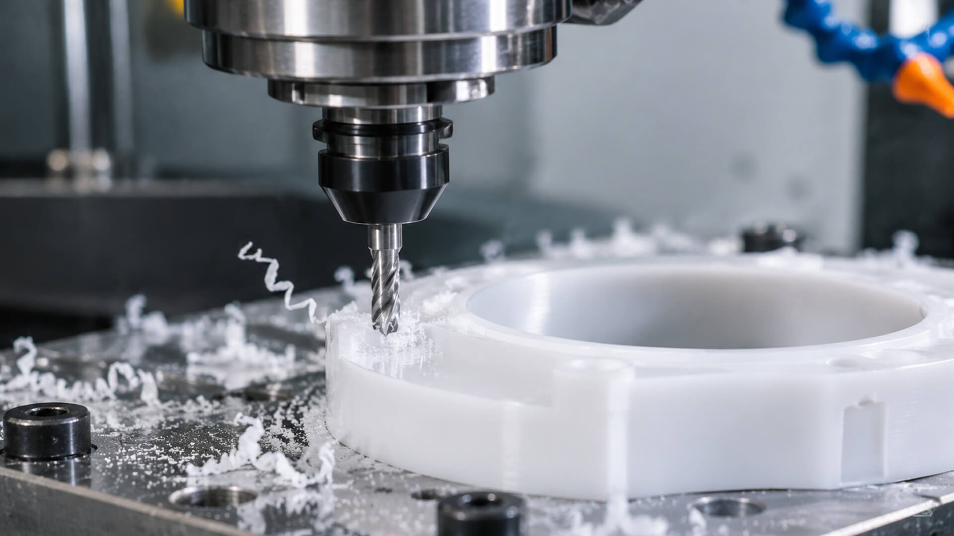
Machining 17-4 PH Stainless Steel: Condition H900 vs. Annealed State, Tooling & Speeds Guide

17-4 PH (AISI 630, UNS S17400, Werkstoff 1.4542) is a martensitic precipitation-hardening stainless steel that bridges the gap between the corrosion resistance of austenitic chromium-nickel alloys and the ultra-high mechanical strength of heat-treated alloy steels. Formulated with nominally 15.0% to 17.5% chromium, 3.0% to 5.0% nickel, 3.0% to 5.0% copper, and 0.15% to 0.45% niobium (columbium), 17-4 PH derives its strength from solid-state precipitation hardening.
In its peak-aged state (Condition H900), fine, coherent sub-microscopic copper-rich clusters (ϵ-phase) precipitate uniformly throughout the low-carbon martensitic lath matrix, pinning dislocation movement and driving yield strength past 1,170 MPa (170 KSI) with a surface hardness reaching 44 HRC.
These mechanical properties make 17-4 PH a foundational alloy across mission-critical sectors:
- Aerospace Structural Airframe Components: Engine pylons, landing gear trunnions, flap tracks, and high-shear structural brackets requiring high strength-to-weight ratios and resistance to stress-corrosion cracking (SCC).
- Surgical & Medical Instruments: Laparoscopic robotic jaws, orthopedic drills, reamers, and spinal fixation devices requiring high edge retention, high torsional stiffness, and resistance to cyclic autoclave sterilization.
- High-Pressure Valve & Chemical Stems: Downhole valve stems, offshore pump shafts, and nuclear reactor coolant components operating under continuous high hydrostatic pressures and abrasive flow.
However, from a subtractive CNC manufacturing standpoint, 17-4 PH presents an engineering trade-off.
Machinability varies dramatically depending on the heat treatment state.
In its soft, solution-annealed state (Condition A / ~30–33 HRC), the material is gummy, highly ductile, and prone to severe built-up edge (BUE) and chip wrapping.
Conversely, in its peak-aged condition (Condition H900 / ~43–45 HRC), cutting forces double (kc≈2,400 to 2,800 N/mm²), localized shear temperatures exceed 800°C (1,472°F), and abrasive flank wear accelerates rapidly, requiring dedicated hard-milling kinematics.
Furthermore, aging 17-4 PH induces a predictable volumetric contraction of 0.04% to 0.06%.
Failing to compensate for this shrinkage during CAM programming guarantees that precision bores, bearing journals, and threaded features will shrink out of print tolerance post-heat treatment.
Navigating these challenges requires parameter discipline, rigid multi-axis machine kinematics, sub-micron coated carbide substrates, and standardized post-machining passivation. Hardware development teams looking for certified flight, medical, or energy components can partner with Celerity Precision through our custom stainless steel machining services.
Table of Contents
Heat Treatment Conditions: Condition A vs. H900 vs. H1025 vs. H1150
Understanding the metallurgical phase state of 17-4 PH is essential before defining tooling or CAM toolpaths. The alloy is supplied from mills in Condition A (Solution Annealed) and is subsequently heat-treated to various aged conditions through a simple, single-step low-temperature aging soak:
Heat Treatment Transformation Timeline: 17-4 PH
Precipitation MetallurgyCondition A (Solution Annealed at 1,040°C / Air Quenched)
Raw PrecursorCondition H900 (Peak Aged)
44 HRC PeakCondition H1150 (Overaged)
33 HRC Tough1. Condition A (Solution Annealed / ~30–35 HRC)
Condition A is produced by heating the raw alloy to 1,040°C (1,904°F) followed by rapid air or oil quenching down to room temperature. This freezes the copper atoms in solid solution within an untempered, low-carbon lath martensitic structure.
While hardness is relatively low, Condition A is not soft like annealed 304 or 316.
It exhibits high tensile ductility and high shear gumminess: chips fail to break naturally, tearing away from the cut face to form severe Built-Up Edge (BUE) on tool tips.
Engineering Alert: Condition A must never be placed into dynamic service without aging. Untempered martensite exhibits low fracture toughness, high residual internal stress, and poor resistance to stress corrosion cracking.
2. Condition H900 (Peak Hardness / ~43–45 HRC)
Condition H900 is achieved by heating Condition A material to 482°C (900°F), soaking for 1 hour, followed by air cooling.
This low-temperature soak triggers the dense, coherent precipitation of copper nano-clusters, producing the alloy’s maximum tensile strength (1,310 MPa / 190 KSI) and surface hardness (up to 45 HRC).
- Machining Dynamics: Specific cutting energy is high, tool-interface temperatures climb rapidly, and abrasive tool wear increases.
- The Machining Benefit: Because ductility is halved, chips become brittle and break naturally into small “C” shapes. Built-up edge is eliminated, allowing machinists to achieve mirror-like surface finishes (Ra≤0.4μm) using rigid tooling and dynamic trochoidal toolpaths.
3. Overaged Conditions: Condition H1025 (~38 HRC) & Condition H1150 (~33 HRC)
Aging at higher temperatures coarsens the copper precipitates (Ostwald ripening), lowering hardness and yield strength while increasing impact toughness and elongation:
- Condition H1025 (Aged at 550°C / 1,025°F for 4 hours): Delivers a balanced trade-off between high tensile strength (~1,070 MPa / 155 KSI) and improved impact resistance. It provides a machinability rating of roughly 50%.
- Condition H1150 (Aged at 621°C / 1,150°F for 4 hours): Overaged state producing moderate hardness (~33 HRC) and high Charpy V-notch impact toughness (often >40 J). It is widely specified for subsea oil and gas valves (NACE MR0175 compliant for sour-gas service) and offers the highest machinability among the heat-treated states (~65%).
| Heat-Treat Condition | Hardness (Rockwell C) |
Tensile (UTS) (MPa / KSI) |
Yield (0.2%) (MPa / KSI) |
Elongation (Break %) |
Machinability (% of 1212) |
Primary Operational Characteristic |
|---|---|---|---|---|---|---|
| Condition A (Solution Annealed) | 30 – 35 HRC | 1,000 MPa (145 KSI) | 790 MPa (115 KSI) | 12% – 17% | ~60% | Gummy cutting mechanics; severe built-up edge (BUE); ductile stringer chip wrapping. |
| Condition H900 (Peak Aged) 44 HRC | 43 – 45 HRC | 1,310 MPa (190 KSI) | 1,170 MPa (170 KSI) | 8% – 12% | ~40% – 45% | Hard-Milling Benchmark: High cutting forces & heat; brittle chips; mirror surface finishes ($Ra \le 0.4 \ \mu\text{m}$). |
| Condition H1025 (Intermediate) | 36 – 40 HRC | 1,070 MPa (155 KSI) | 1,000 MPa (145 KSI) | 12% – 15% | ~50% | Balanced high-tensile strength with elevated impact and fracture toughness. |
| Condition H1150 (Overaged) NACE MR0175 | 31 – 35 HRC | 930 MPa (135 KSI) | 725 MPa (105 KSI) | 16% – 20% | ~65% | Superior stress-corrosion cracking resistance; extended tool life; lower spindle load. |
| Condition H1150M (Double Overaged) | 24 – 29 HRC | 795 MPa (115 KSI) | 520 MPa (75 KSI) | 18% – 24% | ~70% | Maximum ductility and Charpy V-notch toughness for extreme cryogenic and subsea sour environments. |
The Crucial Decision: Pre-Machining vs. Direct Hard-Machining
When planning a 17-4 PH project requiring final Condition H900 properties, manufacturing engineers must select between two primary process routes:
Manufacturing Routing Decision Tree: 17-4 PH
CAM Process PlanningOption A • Two-Stage Routing
Bulk Removal FirstOption B • Direct Hard-Machining
Single-Setup BenchmarkOption A: The Two-Stage Process (Rough in Condition A ➔ Age ➔ Finish in H900)
- The Approach: The component is rough-machined in the softer Condition A state to rapidly clear deep pockets and remove bulk stock. All critical bores, seal faces, and thread locations are left with .30 mm to 0.50 mm (0.012″ to 0.020″) of stock allowance. The semi-machined part is sent to the vacuum oven for H900 aging, then re-fixtured on the CNC machine for final hard-finish milling and grinding.
- The Advantage: Maximizes metal removal rates (MRR) during roughing, limits overall carbide tool wear, and allows heavy internal pocket hogging without excessive spindle load.
- The Drawback: Requires two machine setups, introduces secondary fixture datum alignment challenges, extends production lead times, and incurs outside thermal processing costs.
Option B: Direct Hard-Machining (Single-Setup Cutting from Pre-Hardened H900 Stock)
- The Approach: Raw bar stock or plate is purchased pre-heat-treated from the mill in Condition H900 (44 HRC). The component is cut completely from the solid hardened billet in a single machine setup using high-rigidity CNC machine centers, advanced toolpaths, and dedicated hard-milling carbide end mills.
- The Advantage: Eliminates outside thermal processing, removes secondary setup datum errors, reduces turnaround times, and guarantees that the finished part experiences zero post-machining heat-treatment distortion.
- The Drawback: Requires 50% slower surface speeds, increases cutting tool consumption, and demands high machine tool rigidity and high spindle torque.
Compensating for the 0.05% H900 Dimensional Shrinkage
If Option A is selected, or if a component must be finished complete in Condition A prior to heat treatment, CAM programmers must account for metallurgical contraction:
Linear ShrinkageCondition A to H900 ≈ 0.0004 to 0.0006 mm/mm (0.04% – 0.06%)
During the 482°C aging soak, the precipitation of coherent copper clusters causes the crystal lattice to contract uniformly:
- A 100.00 mm overall length feature will shrink to approximately 99.95 mm post-aging.
- A 25.000 mm diameter bore will shrink by approximately 0.012 mm, closing down bore fits and pinching tapped threads.
- The CAM Protocol: In the CAM environment, apply a global scale factor of 1.0005 (100.05%) to the 3D model prior to generating toolpaths for pre-heat-treat finishing. Once the part contracts in the oven, it pulls into nominal print tolerance.
Speeds, Feeds & Cutting Parameters
Machining 17-4 PH successfully depends on establishing proper cutting parameters for each specific heat treatment condition.
Cutting Condition A at high surface speeds without positive feed generates rapid work hardening and built-up edge.
Conversely, attempting to cut Condition H900 with traditional heavy radial engagements at high speeds will trigger rapid thermal cracking and catastrophic tool chipping.
| Operation & Condition | Tooling Substrate & Coating | Speed (SFM) |
Speed (m/min) |
Chip Load / Feed (FPT / IPR) |
Radial (Ae) | Axial (Ap) |
|---|---|---|---|---|---|---|
| End Milling - Roughing Condition A | Sub-micron Carbide (PVD AlTiN) | 250 – 400 | 75 – 120 | 0.06 – 0.12 mm/tooth | 0.30 – 0.50 × D | 1.00 – 1.50 × D |
| End Milling - Finishing Condition A | Sub-micron Carbide (PVD AlCrN) | 350 – 550 | 105 – 170 | 0.025 – 0.06 mm/tooth | 0.05 – 0.10 × D | 0.50 – 1.00 × D |
| End Milling - Roughing H900 (44 HRC) | Hard-Milling Carbide (AlCrN/TiSiN) | 150 – 250 | 45 – 75 | 0.04 – 0.08 mm/tooth | 0.15 – 0.30 × D | 0.50 – 1.00 × D |
| End Milling - Finishing H900 (44 HRC) | Hard-Milling Carbide (PVD AlTiN) | 220 – 350 | 65 – 105 | 0.02 – 0.04 mm/tooth | 0.03 – 0.06 × D | 0.25 – 0.75 × D |
| Dynamic / Trochoidal HEM Hard | 5-6 Flute Hard-Milling Carbide | 300 – 450 | 90 – 140 | 0.06 – 0.12 mm/tooth | 0.05 – 0.08 × D | 2.00 – 3.00 × D |
| Precision Face Milling H900 (44 HRC) | Heavy-Duty Indexable (PVD AlTiN) | 200 – 320 | 60 – 100 | 0.08 – 0.14 mm/tooth | 0.60 – 0.75 × D | 0.75 – 1.50 mm |
| CNC Turning - Roughing Condition A | Tough ISO Carbide (CNMG/WNMG) | 350 – 550 | 105 – 170 | 0.15 – 0.30 mm/rev | N/A | 1.50 – 3.50 mm |
| CNC Turning - Finishing Condition A | Sharp ISO Carbide (CCGT/DCGT) | 500 – 750 | 150 – 230 | 0.05 – 0.12 mm/rev | N/A | 0.25 – 0.75 mm |
| CNC Turning - Roughing H900 (44 HRC) | Micro-Grain Carbide (CNMG/WNMG) | 180 – 300 | 55 – 90 | 0.10 – 0.20 mm/rev | N/A | 1.00 – 2.00 mm |
| CNC Turning - Finishing H900 (44 HRC) | Hard-Turning Carbide (CCGT/VBMT) | 280 – 450 | 85 – 140 | 0.03 – 0.08 mm/rev | N/A | 0.15 – 0.40 mm |
| Standard Twist Drilling Condition A | Polished Parabolic Carbide Drill | 150 – 250 | 45 – 75 | 0.06 – 0.12 mm/rev | Full Drill D | 1.00 – 2.00 × D (Peck) |
| Standard Twist Drilling H900 (44 HRC) | Heavy-Web Hard-Drilling Carbide | 90 – 160 | 28 – 50 | 0.03 – 0.07 mm/rev | Full Drill D | 0.50 – 1.00 × D (Peck) |
Dynamic / Trochoidal Milling (High-Efficiency Milling) in H900
When machining hardened 17-4 PH (44 HRC), traditional heavy-radial milling generates excessive heat, deflecting the cutter and dulling tools rapidly.
Instead, high-performance shops use dynamic/trochoidal milling:
- Low Radial Engagement (Aₑ=5% to 8% of Cutter Diameter): By keeping the radial stepover light, the cutter’s radial angle of engagement drops to under 35 degrees. Each tooth cuts for a brief instant before rotating through a long cooling phase, during which high-pressure coolant washes the cutting edge to reduce localized temperatures.
- Extended Axial Engagement (Aₚ=2.0 to 3.0×D): Utilizing the full flute length distributes mechanical wear across the entire carbide edge rather than concentrating all thermal fatigue on the bottom corner of the end mill, extending tool life by 300% to 500%.
- Chip Thinning Compensation: Programmers must calculate the effective chip thickness (hₑₓ) at light radial stepovers and boost programmed table feed rates to ensure the cutting edge shears rather than rubs, preventing work hardening.
Tooling Physics & Substrate Selection for 44 HRC Stainless
Cutting martensitic stainless steel heat-treated to 44 HRC requires tooling designed for hard-metal cutting:
Tooling Geometry for Condition H900 (44 HRC)
Hard-Milling Specification1. The Cutting Edge Preparation: T-Lands and Negative Rakes
- The Failure of Sharp Razor Edges in H900: A razor-sharp cutting edge (rβ<3μm) lacks sufficient structural backing to support the high mechanical shear forces (kc ≈ 2,600 N/mm²) generated by 44 HRC stainless. Under dynamic load, a sharp edge will micro-chip within seconds.
- The T-Land Chamfer (Negative Land): Cutting tools for H900 must feature a precision negative chamfer (T-land) measuring .03 mm to 0.05 mm wide at an angle of 15° to 20°, followed by a light micro-hone (rβ≈10 to15 μm). This negative land redirects cutting forces inward as compressive stresses into the core of the carbide insert, where tungsten carbide exhibits its highest fracture strength.
- Rake Angle Strategy: Specify neutral (0°) to slightly negative (-2° to -5°) axial and radial rake angles for roughing H900. For softer Condition A, switch to positive rake angles (+8° to +12°) to slice through gummy, ductile chips and prevent built-up edge (BUE).
2. Carbide Substrates & Nano-Composite PVD Coatings
- Ultra-Fine Sub-Micron Substrate: Use sub-micron grain solid tungsten carbide (grain size 0.4 µm to 0.7 µm) bound with 10% to 12% cobalt (Co). This formulation provides high hot hardness along with the transverse rupture strength (TRS > 4,000 MPa) required to withstand mechanical shock loads during interrupted cuts.
- Advanced Multi-Layer PVD Coatings: Avoid standard single-layer TiN or CVD coatings. Use advanced physical vapor deposition (PVD) nano-composite coatings:
- PVD AlCrN (Aluminum Chromium Nitride): Provides oxidation resistance up to 1,100°C (2,012°F) and low chemical affinity for chromium-nickel alloys. Under high cutting heat, AlCrN forms an ultra-dense, self-healing chromium oxide (Cr₂O₃) thermal barrier on the rake face.
- PVD AlTiN / TiSiN: Titanium Silicon Nitride nano-composite coatings deliver a surface micro-hardness exceeding 3,600 HV, resisting abrasive tool wear in hardened H900.
Coolant Strategies: High-Pressure Coolant (HPC)
Traditional low-pressure flood coolant delivered at 3 to 5 bar is largely ineffective when hard-milling 17-4 PH at 44 HRC. At interface temperatures exceeding 800°C, low-pressure coolant boils before reaching the cutting edge.
A microscopic vapor barrier (the Leidenfrost Effect) forms, insulating the cutting zone and allowing the tool edge to run hot and dry.
When coolant splashes against the superheated carbide, the resulting thermal shock produces comb-like thermal cracks perpendicular to the cutting edge, leading to chipping and tool fracture.
Conventional Flood vs. High-Pressure Coolant (HPC)
Thermodynamic Fluid MechanicsConventional Flood Coolant
Comb Cracking RiskHigh-Pressure Coolant (HPC)
Hard-Milling StandardAt Celerity Precision, hard stainless machining is supported by High-Pressure Through-Spindle Coolant (HPC) operating at 70 to 100 bar (1,000 to 1,500 PSI):
- Hydraulic Vapor Barrier Penetration: High-velocity micro-jets emerge millimeters from the cutting edge, using kinetic energy to pierce the steam blanket and deliver liquid lubricant directly to the tool-chip interface.
- Thermal Stabilization: HPC delivery drops localized cutting edge temperatures by 150°C to 200°C, preventing the cobalt binder from softening and eliminating the thermal shock cycles that cause comb cracking.
- Hydraulic Chip Evacuation: In deep internal pockets, the concentrated hydraulic force curls ductile chips into tight spirals and flushes them clear of the toolpath, preventing the destructive recutting of work-hardened stainless chips.
- Fluid Concentration Control: Maintain a strict 10% to 12% concentration of high-lubricity, chlorine-free semi-synthetic or ester-based water-soluble emulsion. Monitor concentration daily using digital refractometers.
High-Rigidity Production on Celerity Shop-Floor Equipment
Cutting 44 HRC martensitic stainless steel generates high dynamic cutting forces ( kc ≈ 2,600 N/mm²). Any structural compliance or dynamic runout within the machine spindle, toolholder, or workholding fixture will excite regenerative chatter.
In hardened 17-4 PH, chatter chips carbide cutting edges within seconds, destroys surface finishes, and induces work-hardened surface layers that ruin subsequent passes.
At Celerity Precision, 17-4 PH components are routed across dedicated, high-rigidity machining platforms:
1. Simultaneous 5-Axis Centers (German Hermle C400 & DMG MORI DMU 50)
For complex aerospace structural brackets, medical instruments, and valve manifolds:
- Mineral-Cast Polymer Concrete Beds: Our German Hermle C400 and DMG MORI DMU 50 centers utilize mineral-cast bases. Polymer concrete provides dynamic structural damping up to 10 times higher than welded steel structures, absorbing the high-frequency harmonics generated by hard-milling 44 HRC material.
- Single-Setup Multi-Axis Alignment: Simultaneous 5-axis capabilities allow multi-sided parts to be machined in a single clamping setup. Eliminating secondary setups removes cumulative datum stack-up errors, ensuring hole concentricities and true-position tolerances down to ±0.005 mm (±0.0002″).
- Tool Overhang Optimization: 5-axis kinematics allow tools to be tilted relative to the cut, letting machinists deploy short, rigid end mills (L/D ≤ 3:1) into deep cavities instead of long, flexible reach tools that chatter.
2. High-Torque Production Kinematics (Makino a40 Horizontal Centers)
For production runs of valve stems, pump bodies, and aerospace fittings:
- High-Torque Spindle Rigidity: Our Makino a40 horizontal machining centers utilize rigid stepped-column structures and dual-supported ball screws, maintaining structural alignment under heavy radial cutting loads.
- Gravity-Assisted Chip Evacuation: The horizontal spindle orientation allows heavy chip streams to fall away under gravity directly into the chip conveyor, eliminating chip recutting in deep cavities.
3. Thermal Induction Shrink-Fit Toolholding
Standard split-collet chucks (such as ER collets) are unsuited for hard 17-4 PH machining. Under heavy cutting forces and micro-vibration, split collets allow microscopic axial tool slip (“pullout”), dragging the cutter deeper into the workpiece.
- Shrink-Fit Mandate: We secure cutting tools in thermal induction shrink-fit toolholders. Shrink-fit systems clamp 360 degrees around the ground carbide shank, delivering dynamic runout verified under .003 mm (0.0001″) at 3×D, combined with high gripping torque and rotational balance (G2.5 at 25,000 RPM).
To review our complete production floor capabilities, inspect our precision CNC milling capabilities.
Quality Assurance & ASTM A967 Chemical Passivation
Precision 17-4 PH parts for aerospace, medical, and high-pressure chemical service require rigorous metrology and surface treatment to ensure dimensional accuracy and corrosion resistance:
ASTM A967 Chemical Passivation Workflow: 17-4 PH
Corrosion Inhibition QA / ASTM A9671. Zeiss CMM Dimensional Inspection
Spatial dimensional verification is conducted in our dedicated metrology laboratory, maintained at 20°C ± 1°C (68°F ± 1.8°F):
- Thermal Soak Normalization: Finished components soak in the metrology room for a minimum of 4 to 8 hours to reach thermal equilibrium before probing.
- Zeiss Scanning Contact Metrology: Spatial dimensions, true-position hole locations, and complex 3D profiles are verified on our bridge-type Zeiss CMM. Scanning probes map critical features down to verified tolerances of ±0.005 mm (±0.0002″).
- Optical Profilometry: Surface roughness on sealing lands and bearing journals is verified with contact stylus and non-contact optical profilometers, confirming target finishes (Ra≤0.4 μm) without manual bench polishing.
2. Raw Material Lot Verification via XRF Spectroscopy
A persistent risk in precision manufacturing is receiving mislabeled material. Generic austenitic 304 or 316 stainless steels can be inadvertently substituted for 17-4 PH bar stock.
If a part machined from 304 is sent to an oven for H900 heat treatment, it will fail to harden, remaining soft at ~20 HRC and risking structural failure in high-load assemblies.
To protect customer supply chains, Celerity Precision inspects incoming raw bar, rod, and billet material using an on-site X-Ray Fluorescence (XRF) Spectrometer / Analyzer:
- Chemical Lot Profiling: Every material lot undergoes spectroscopic analysis to verify primary elemental ratios:
- Chromium (Cr): 15.00% to 17.50%
- Nickel (Ni): 3.00% to 5.00%
- Copper (Cu): 3.00% to 5.00% (The critical precipitation-hardening element)
- Niobium (Nb): 0.15% to 0.45%
- Silicon & Manganese: <1.00% each; Balance Iron.
- Certification Traceability: Spectroscopic lot signatures are cross-referenced directly against certified Mill Test Reports (MTRs), ensuring complete material traceability from the raw melt to the final shipped part.
3. Post-Machining Passivation Compliant with ASTM A967
During CNC machining, carbide cutting tools and steel fixturing shed microscopic particles of elemental free iron that embed into the surface of the 17-4 PH part. In corrosive operating environments, this tramp iron breaks down the stainless steel’s passive layer, generating surface rust spots and initiating localized pitting corrosion.
To restore corrosion resistance, components undergo standardized chemical passivation per ASTM A967:
- Citric Acid Passivation (Preferred for 17-4 PH): Citric acid formulations (such as ASTM A967 Citric 4) are preferred over traditional nitric acid for precipitation-hardened grades. Citric acid selectively targets and dissolves surface free iron without leaching out the critical 4% copper phase, eliminating the dark surface etching and smutting common with nitric acid baths.
- Process Parameters: Components are ultrasonically degreased, submerged in an aqueous citric acid bath (4% to 10% citric acid by weight) heated to 50°C to 60°C (122°F to 140°F) for 20 to 30 minutes, rinsed thoroughly in pure deionized water, and dried with clean forced air.
- Corrosion Barrier Restoration: Passivation exposes the surface chromium atoms to atmospheric oxygen, forming a continuous, self-healing chromium-oxide (Cr₂O₃) passive barrier that protects the component across its operational lifecycle. Review our complete post-processing capabilities on our metal passivation finishing page.
DFM Rules for Cost-Effective 17-4 PH Parts
Because 17-4 PH is a high-strength, abrasive alloy with longer machine cycle times than standard stainless steels, disciplined Design for Manufacturability (DFM) significantly reduces unit production costs:
1. Specify Thread Milling Over Cut Tapping for Hardened Blind Holes
Tapping blind threads smaller than M5 (or #10-32) in Condition H900 (44 HRC) with traditional fluted taps carries a high risk of tool breakage. The hardened alloy chips and binds in the tap flutes, snapping the tap inside the hole.
- DFM Rule: Design tapped hole depths to a maximum of 1.5×D to 2.0×D. Where blind internal threads are required in hardened 17-4 PH, specify thread milling on the drawing. Thread milling allows chips to evacuate freely up the hole, reduces cutting forces, and allows a worn cutter to be replaced easily without scrapping a high-value housing.
2. Design Generous Internal Cavity Fillets (R ≥ 1.0 mm to 1.5 mm)
Designing sharp, 90-degree internal vertical corners (R<0.5 mm) inside deep pockets forces machine shops to use small-diameter micro-end mills. Small cutters run at reduced feed rates and deflect easily when cutting 44 HRC material, increasing machining time and risking corner chatter.
- DFM Rule: Design internal pocket corners with a radius of at least R≥1.00 mm (0.040″), and ideally R≥1.5 × tool radius. Generous fillets allow rigid end mills to maintain continuous trochoidal toolpaths through corners without pausing, preventing localized heat buildup and premature tool wear.
3. Maintain Balanced Structural Wall Thicknesses (≥ 1.0 mm)
While 17-4 PH is stiff (elastic modulus ~196 GPa), cutting forces in Condition H900 are high (kc ≈ 2,600 N/mm²). Thin vertical walls (<0.8 mm) deflect elastically away from the cutter during machining passes, causing wall taper, chatter, and dimensional variation.
- DFM Rule: Maintain structural wall thicknesses ≥1.20 mm to 1.50 mm (0.048″ to 0.060″) wherever possible. If thin aero-style ribs (<1.0 mm) are essential, design structural support gussets or a 1° to 2° draft angle along the wall base to resist cutter deflection forces.
4. Select the Optimal Heat Treatment Condition for Functional Requirements
Specifying Condition H900 across an entire component when only moderate strength is functionally required drives up machining cycle times and tool consumption.
- DFM Rule: Evaluate functional mechanical requirements carefully. If extreme yield strength (1,170 MPa) is not essential, consider specifying Condition H1025 (~38 HRC) or Condition H1150 (~33 HRC). Overaged conditions reduce cutting forces, extend tool life, and lower overall component machining costs by 20% to 35% while providing superior fracture toughness.
Precision 17-4 PH Manufacturing for Flight & Surgical Hardware
Machining 17-4 PH stainless steel to tight tolerances requires moving past trial-and-error setups. Repeatable production demands matching alloy metallurgy with appropriate manufacturing controls: understanding the differences between Condition A and H900, accounting for post-aging dimensional shrinkage, utilizing rigid 5-axis machine platforms, deploying high-pressure through-spindle coolant, and executing ASTM A967 chemical passivation.
Whether your assembly requires complex surgical instrument bodies milled on our precision CNC milling capabilities centers or high-pressure aerospace structural brackets produced through our custom stainless steel machining services cells, Celerity Precision delivers repeatable, tight-tolerance components backed by material certifications and Zeiss CMM inspection reports.
Request a Comprehensive DFM Analysis and Precision 17-4 PH Quote
Submit your 3D CAD models (STEP, IGS) and 2D engineering drawings to our aerospace and medical applications team. We will deliver an engineering-grade manufacturability review within 24 hours, evaluating heat-treatment routing (Condition A vs. H900 pre-hardened), shrinkage compensation, toolpath feasibility, and transparent factory-direct pricing.
- Strict Non-Disclosure Agreement (NDA) Protection
- 4-Hour Engineering DFM & Quotation Turnaround
- Zeiss CMM Dimensional Inspection & ASTM A967 Passivation Certification
Upload your CAD drawings via our contact page to begin your project review with our engineering team.

CP Engineering Team
Authored and peer-reviewed by the Senior Engineering and Metrology Team at Celerity Precision. Backed by German 5-axis CNC machining centers, high-speed micro-milling platforms, and a climate-controlled Zeiss CMM inspection lab, our team delivers deep DFM insights, material machinability guides, and precision manufacturing solutions for aerospace, medical, and semiconductor developers worldwide.