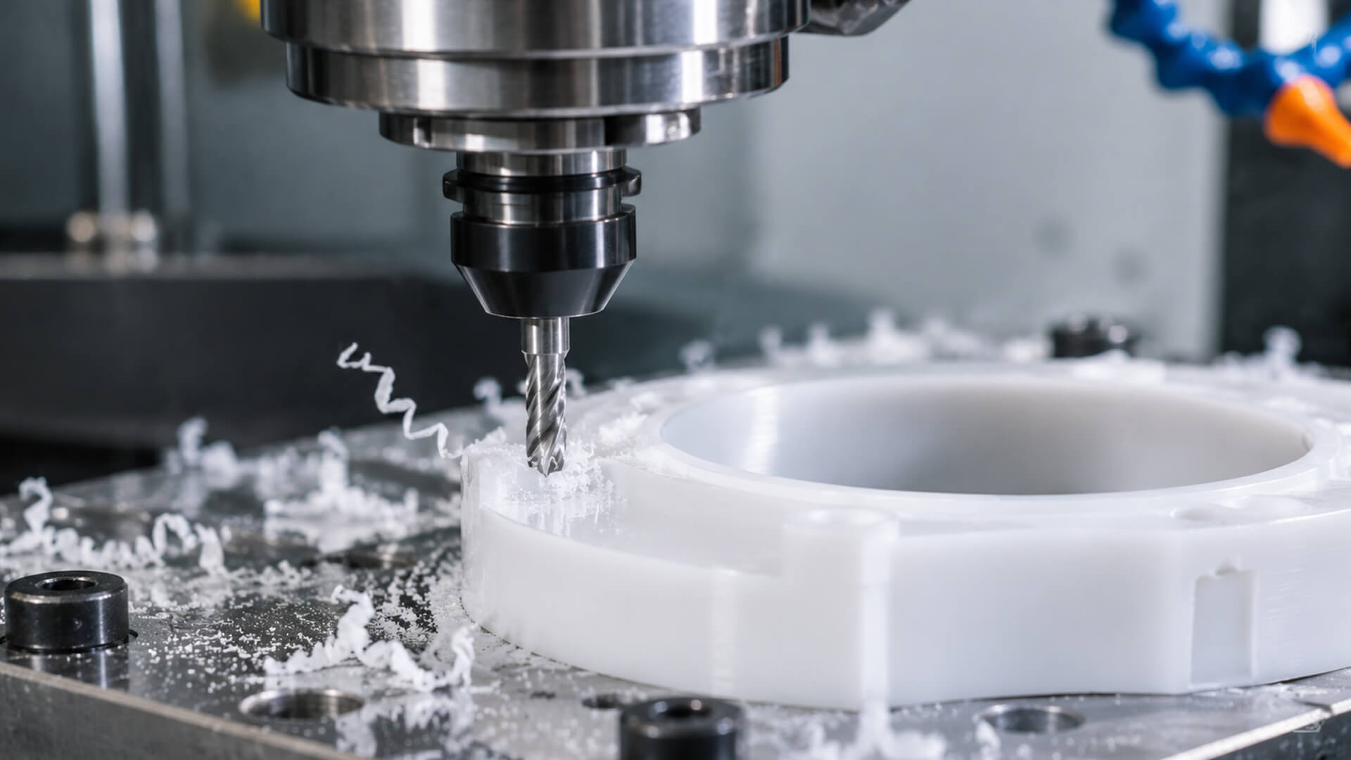
Machining Molybdenum & Tungsten: Feeds, Speeds, Tooling & Brittle Fracture Prevention Guide

Refractory metals—anchored by molybdenum (Mo) and tungsten (W)—represent the absolute thermodynamic extreme of metallic subtractive manufacturing. Operating in environments where conventional high-temperature alloys like Inconel, titanium, and cobalt-chrome melt, creep, or sublimate, these refractory elements are defined by extreme melting points (2,623°C / 4,753°F for molybdenum and 3,422°C / 6,192°F for tungsten), high elastic moduli (E≈320 GPa for Mo and E≈410 GPa for W), low thermal expansion coefficients, and resistance to high-energy plasma erosion.
These mechanical and thermal properties make molybdenum and tungsten indispensable across mission-critical technologies:
- Semiconductor Ion Implantation & Photolithography: Sputtering targets, ion source chambers, arc chambers, extraction electrodes, and beam-defining apertures requiring thermal dimensional stability and resistance to corrosive fluoride gases.
- Medical Diagnostic Imaging & Radiotherapy: High-density multi-leaf collimators (MLCs), X-ray tube rotating anodes, and radioisotope shielding components that exploit tungsten’s extreme density (19.3 g/cm³, matching gold) for radiation attenuation.
- Aerospace Propulsion & High-Vacuum Furnaces: Rocket nozzle throats, re-entry thermal shields, vacuum furnace heating elements, and radiation shielding barriers operating at temperatures exceeding 1,600°C to 2,200°C.
However, in standard machine shops, molybdenum and tungsten are often treated as unmachinable.
Both elements crystallize in a body-centered cubic (BCC) crystal lattice. Unlike face-centered cubic (FCC) metals that retain ductility across broad thermal ranges, BCC refractory metals exhibit a sharp Ductile-to-Brittle Transition Temperature (DBTT).
At ambient room temperature, unalloyed tungsten is brittle; cutting it with conventional milling toolpaths causes intergranular micro-cracking, catastrophic breakout at tool exit planes, and rapid tool destruction.
Molybdenum, while machinable at room temperature, is abrasive, notch-sensitive, and prone to sheet delamination along fibrous grain boundaries.
Navigating these challenges requires specialized cutter geometries, vibration-damping machine platforms, sacrificial edge-supporting fixturing, and strict raw material density validation. Hardware engineering teams looking for certified aerospace, semiconductor, or medical components can partner with Celerity Precision through our custom CNC machining capabilities.
Table of Contents
Metallurgical Comparison: Pure Elements vs. Engineered Alloys
Specifying refractory stock requires matching the specific metallurgical state—powder-metallurgy sintered, arc-cast, or liquid-phase sintered alloy—to the component’s mechanical and machining requirements:
- DBTT: 200°C – 400°C ──► Fully brittle at room temp
- Failure Mode: Grain cleavage, edge spalling, chipping
- Microstructure: 90-97% W spheres in ductile Ni-Fe
- Machinability: High (~60%) ──► Conventional carbide
- Recrystallization Temp: 1,400°C (vs. 1,150°C pure Mo)
- Carbide Dispersions ──► High creep strength, abrasive
1. Pure Molybdenum vs. TZM Alloy
- Pure Molybdenum (ASTM B387 Type 361): Unalloyed molybdenum exhibits high electrical conductivity, excellent thermal conductivity (138 W/(m·K)), and good machinability at room temperature. However, it begins to recrystallize and embrittle at approximately 1,150°C (2,102°F). During machining, pure molybdenum produces fine, flaky chips that can adhere to the cutting edge, requiring extreme-pressure lubrication to prevent galling.
- TZM Alloy (Titanium-Zirconium-Molybdenum, ASTM B387 Type 364): Formulated with 0.50% titanium, 0.08% zirconium, and roughly 0.02% carbon. The fine dispersion of complex titanium-zirconium carbides pins grain boundaries, raising the recrystallization temperature to 1,400°C (2,552°F) and doubling creep strength at 1,200°C.
From a machining perspective, TZM is substantially harder and more abrasive than pure molybdenum, requiring rigid machine setups and wear-resistant PVD coatings to maintain edge integrity.
2. Pure Tungsten vs. Tungsten Heavy Alloys (W-Ni-Fe / Densalloy)
- Pure Tungsten (ASTM B760): Produced via powder-metallurgy pressing and sintering (often followed by swaging), pure tungsten features an extremely high DBTT (200°C to 400°C / 392°F to 752°F). At standard room temperature (20°C), pure tungsten cannot plastically deform to relieve cutting stresses. Cutting forces trigger micro-cracks along brittle grain boundaries, causing the material to chip and crumble ahead of the tool. Precision machining of pure tungsten requires warm-machining setups (preheating stock to 300°C–400°C) or specialized PCD tooling.
- Tungsten Heavy Alloys (W-Ni-Fe / W-Ni-Cu, ASTM B777 Classes 1–4): Engineered to overcome pure tungsten’s brittleness, these alloys are produced via liquid-phase sintering. They consist of 90% to 97% spherical tungsten particles embedded within a continuous, ductile matrix of nickel-iron or nickel-copper.
The ductile FCC matrix absorbs shear strains and blunts micro-cracks, lowering the DBTT below room temperature.
Tungsten heavy alloys machine similarly to high-strength alloy steels, producing continuous curling chips and clean surface finishes (Ra≤ 0.4 μm) using standard coated carbide tooling.
- Tungsten Copper (W-Cu Pseudo-Alloy): Sintered porous tungsten skeletons infiltrated with 10% to 30% liquid copper. Widely specified for EDM spark-erosion electrodes and high-voltage electrical contacts, W-Cu machines cleanly because the soft copper phase acts as an internal lubricant and chip breaker.
| Refractory Material Grade | Nominal Composition | Density (g/cm³) | Hardness (Room Temp) | DBTT Range (°C) | Relative Machinability (%) | Primary Operational Characteristic |
|---|---|---|---|---|---|---|
| Pure Molybdenum (ASTM B387) | 99.95% Mo | 10.22 g/cm³ | 200 – 240 HV (90 HRB) | 20°C – 100°C | ~45% | Gummy chip tendencies; susceptible to exit-edge breakout. |
| TZM Moly Alloy (ASTM B387) | Mo-0.5Ti-0.08Zr-0.02C | 10.15 g/cm³ | 280 – 320 HV (30 HRC) | -20°C – 50°C | ~35% | High abrasive carbide tool wear; excellent high-temperature creep strength. |
| Pure Tungsten (ASTM B760) | 99.95% W | 19.25 g/cm³ | 400 – 480 HV (45 HRC) | 200°C – 400°C | ~15% – 20% | Brittle at room temperature; requires warm machining or PCD diamond. |
| Tungsten Heavy Alloy (Class 1-4) | 90%–97% W, Bal. Ni-Fe | 17.0 – 18.5 g/cm³ | 300 – 360 HV (32–38 HRC) | Below 0°C | ~60% | Excellent machinability; ductile matrix; primary radiation shielding alloy. |
| Tungsten Copper (W-Cu 80/20) | 80% W, 20% Cu | 15.2 – 15.6 g/cm³ | 220 – 260 HV (98 HRB) | Below 0°C | ~70% | High thermal conductivity; free-cutting matrix; EDM electrode benchmark. |
The Primary Failure Mode: Edge Chipping & Laminations
When milling or turning molybdenum and pure tungsten, the primary source of scrapped parts is exit-edge breakout (chipping/spalling) and cross-grain delamination.
Mechanics of Exit-Edge Breakout (Spalling)
1. The Physics of Exit-Edge Breakout
As an end mill or turning tool cuts toward the edge of a refractory metal workpiece, the volume of supporting material ahead of the tool decreases.
In ductile metals like aluminum or brass, the material deforms plastically into an exit burr.
In molybdenum and tungsten, the tensile stresses concentrated ahead of the cutting edge exceed the material’s grain-boundary cleavage strength before plastic shear can occur.
Instead of cutting cleanly through the edge, the cutter pushes the unsupported corner outward, causing a brittle fracture that tears off a chunk of material (breakout depths frequently reach 0.5 mm to 2.0 mm).
2. The Delamination Threat in Rolled Molybdenum Sheet
Rolled molybdenum plates and sheets feature an elongated, fibrous grain structure oriented parallel to the rolling direction. The inter-lamellar bonding strength perpendicular to the rolling plane (the Z-axis) is low.
When drilling through-holes or face milling parallel to these fiber planes, vertical cutting forces can peel the grain boundaries apart, producing sub-surface delamination cracks that ruin vacuum hermeticity.
3. Engineering Countermeasures to Prevent Breakout
To eliminate exit breakout and delamination during CNC production:
- Roll-In / Roll-Out Toolpath Kinematics: Never program an end mill to exit a refractory metal workpiece along a straight line perpendicular to the edge. Program sweeping roll-out arc toolpaths that gradually reduce radial engagement (Ae) to zero before the cutter crosses the boundary.
- Sacrificial Backing Plates: When drilling through-holes or face milling perimeter edges, clamp a sacrificial backing plate tightly against the exit face of the part. Aluminum tooling plate or scrap molybdenum sheet clamped against the breakthrough face provides physical support, keeping the edge in compression until the tool clears the cut.
- Chamfer Prior to Facing: Before executing final face-milling passes across a rectangular block, machine a 1.0 mm×45° lead chamfer along all peripheral exit edges. This pre-chamfer ensures the milling tooth exits into an open angle, preventing corner blowouts.
- Climb Milling (Down Milling) Mandate: Always utilize climb milling. Climb milling directs cutting forces into the bulk of the workpiece at the entry point and thins the chip out to zero thickness at the exit, minimizing tensile breakout stresses.
Speeds, Feeds & Cutting Parameters
Machining refractory metals requires strict parameter control: low-to-moderate surface cutting speeds, positive continuous chip loads, and rigid toolpaths.
Dwelling or running an inadequate feed per tooth burnishes the surface, accelerates work hardening, and dulls the cutting edge within seconds.
The following parameter matrix outlines validated starting baselines across annealed pure molybdenum, TZM alloy, and Class 1–4 tungsten heavy alloys:
| Machining Operation | Material Grade | Tooling Substrate & Coating | Cutting Speed (SFM) | Cutting Speed (m/min) | Chip Load / Feed | Radial Width (Ae) | Axial Depth (Ap) |
|---|---|---|---|---|---|---|---|
| End Milling - Roughing | Pure Molybdenum | Sub-micron Solid Carbide (PVD TiAlN) | 150 – 250 | 45 – 75 | 0.04 – 0.08 mm/tooth | 0.30 – 0.50 × D | 0.75 – 1.25 × D |
| End Milling - Finishing | Pure Molybdenum | Sub-micron Solid Carbide (PVD AlCrN) | 200 – 350 | 60 – 105 | 0.02 – 0.05 mm/tooth | 0.05 – 0.10 × D | 0.25 – 0.75 × D |
| End Milling - Roughing | TZM Moly Alloy | High-Performance Carbide (AlCrN/TiSiN) | 120 – 200 | 36 – 60 | 0.03 – 0.07 mm/tooth | 0.20 – 0.40 × D | 0.50 – 1.00 × D |
| End Milling - Finishing | TZM Moly Alloy | Sub-micron Solid Carbide (PVD AlCrN) | 180 – 280 | 55 – 85 | 0.015 – 0.04 mm/tooth | 0.04 – 0.08 × D | 0.20 – 0.50 × D |
| End Milling - Roughing | Tungsten Heavy Alloy | Micro-Grain Carbide (PVD TiAlN/AlCrN) | 200 – 350 | 60 – 105 | 0.05 – 0.10 mm/tooth | 0.30 – 0.50 × D | 0.75 – 1.50 × D |
| End Milling - Finishing | Tungsten Heavy Alloy | Micro-Grain Carbide (PVD TiCN) | 300 – 500 | 90 – 150 | 0.025 – 0.06 mm/tooth | 0.05 – 0.10 × D | 0.25 – 0.75 × D |
| CNC Turning - Roughing | Pure Molybdenum | Tough ISO Carbide (CNMG/WNMG) | 200 – 350 | 60 – 105 | 0.12 – 0.25 mm/rev | N/A | 1.00 – 2.50 mm |
| CNC Turning - Finishing | Pure Molybdenum | Sharp ISO Carbide (CCGT/DCGT) | 300 – 500 | 90 – 150 | 0.04 – 0.08 mm/rev | N/A | 0.20 – 0.50 mm |
| CNC Turning - Roughing | Tungsten Heavy Alloy | Micro-Grain Carbide (CNMG/WNMG) | 250 – 450 | 75 – 135 | 0.15 – 0.30 mm/rev | N/A | 1.50 – 3.00 mm |
| CNC Turning - Finishing | Tungsten Heavy Alloy | Hard-Turning Carbide (CCGT/VBMT) | 400 – 650 | 120 – 200 | 0.05 – 0.10 mm/rev | N/A | 0.25 – 0.60 mm |
| Twist Drilling (Carbide) | Pure Mo / TZM | Polished Parabolic Carbide Drill | 80 – 150 | 25 – 45 | 0.04 – 0.08 mm/rev | Full Drill D | 0.50 – 1.00 × D (Peck) |
| Twist Drilling (Carbide) | Tungsten Heavy Alloy | Micro-Grain Coated Carbide Drill | 120 – 220 | 36 – 65 | 0.06 – 0.12 mm/rev | Full Drill D | 0.75 – 1.50 × D (Peck) |
| Pure Tungsten Cutting | Pure Sintered Tungsten | PCD Tipped (Preheat 300°C) | 100 – 180 | 30 – 55 | 0.02 – 0.05 mm/tooth | 0.10 – 0.20 × D | 0.20 – 0.50 mm |
Tooling Physics & Edge Preparation for Refractory Metals
Standard cutting tool geometries designed for carbon steel or general-purpose alloys fail quickly in refractory metals.
The combination of high specific cutting forces ( kc≈ 2,200 to 2,800 N/mm²), severe abrasive tool wear, and high mechanical shock loads requires specialized tooling substrates and edge conditioning:
Optimized Cutter Geometry for Molybdenum & TZM
1. The Cutting Edge Preparation: Micro-Honing vs. Razor Edges
- The Danger of Unhoned Razor Edges: A dead-sharp cutting edge (rβ< 3 μm) lacks sufficient structural backing to withstand the mechanical shocks caused by refractory grain boundary cleavage. Under dynamic load, an unhoned edge will micro-chip along its perimeter, accelerating notch wear and tearing the workpiece surface.
- The Precision Micro-Hone: Tooling must feature a precision-controlled micro-hone (rβ=10 to 15 μm). This slight, controlled rounding stabilizes the cutting wedge, distributing mechanical stresses across a larger cross-section of the carbide substrate without increasing plowing forces.
- Rake and Relief Angles: Specify positive radial and axial rake angles between +6° and +10°. Positive rake angles reduce shear resistance and lift chips cleanly off the workpiece. Primary clearance angles must be maintained between +8° and +12° to eliminate friction between the work-hardened cut face and the tool flank.
2. Carbide Substrates & Diamond (PCD) Tooling
- Sub-Micron Tungsten Carbide (WC-Co): For milling pure molybdenum, TZM, and tungsten heavy alloys, use ultra-fine sub-micron grain solid carbide (grain size 0.4 µm to 0.7 µm) bound with 10% to 12% cobalt. Higher cobalt content provides the transverse rupture strength (TRS > 4,000 MPa) required to resist mechanical chipping when the tool enters and exits cuts.
- Polycrystalline Diamond (PCD) for Sintered Pure Tungsten: Pure sintered tungsten abrades standard carbide within minutes. For pure tungsten components, deploy fine-grain (2 µm to 5 µm) Polycrystalline Diamond (PCD) or thick CVD diamond-coated tooling. PCD’s micro-hardness (>8,000 HV) resists severe abrasive grain wear, maintaining nominal drawing dimensions across production runs.
- High-Performance PVD Coatings: Avoid thick CVD coatings; chemical vapor deposition temperatures embrittle fine-grained carbide substrates. Use thin (2 µm to 4 µm), low-stress PVD nano-composite coatings:
- PVD AlCrN (Aluminum Chromium Nitride): Provides oxidation stability up to 1,100°C and low chemical affinity for refractory metals, resisting adhesive wear.
- PVD TiSiN (Titanium Silicon Nitride): Delivers surface micro-hardness exceeding 3,600 HV, resisting abrasive micro-grooving during heavy roughing of TZM alloy.
Coolant Discipline & Thermal Shock Prevention
Thermal management in refractory metal machining requires balancing chemical lubrication with thermal shock prevention:
Thermal Cracking Mechanics in Pure Tungsten
Thermal Fatigue & Comb Cracking Failure Mechanism1. Coolant Strategy: Molybdenum & TZM vs. Pure Tungsten
- Molybdenum and TZM (Heavy-Duty Extreme-Pressure Emulsions): Molybdenum tends to tear and gall during machining. Flood the cutting zone with heavy-duty, water-soluble semi-synthetic emulsions mixed at 10% to 12% concentration, equipped with active extreme-pressure (EP) chlorinated or ester-based boundary additives.
High-pressure delivery (70 to 100 bar / 1,000+ PSI) flushes abrasive refractory fines away from the cut, preventing the recutting of work-hardened particles. For blind-hole tapping and micro-threading, apply heavy-duty sulfurized/chlorinated neat cutting oils directly to the tool.
- Pure Sintered Tungsten (Continuous Flood vs. Controlled Dry Cutting): Pure tungsten is sensitive to thermal shock cracking.
If a low-pressure coolant stream intermittently splashes against a tungsten workpiece operating at 700°C+, the sudden localized temperature drops create steep thermal gradients.
The brittle tungsten substrate experiences thermal contraction shock, producing fine micro-cracks (comb cracking) across the component.
- The Pure Tungsten Rule: Cut pure tungsten either completely dry with a continuous high-velocity vortex air blast (-10°C) to clear abrasive dust, or under continuous, flood-volume coolant that never interrupts fluid coverage across the cut. Never allow coolant to splash intermittently onto hot tungsten.
High-Rigidity Production on Celerity Shop-Floor Equipment
Machining high-density refractory metals ( 10.2 to19.3 g/cm³) generates high specific cutting forces and mechanical shock loads. Any dynamic compliance within the machine spindle, toolholder, or fixturing setup will excite regenerative chatter.
In brittle refractory metals, chatter causes immediate edge breakout, chips tools, and induces sub-surface micro-cracking.
At Celerity Precision, refractory components are routed across dedicated, high-rigidity machining platforms:
1. High-Damping Simultaneous 5-Axis Platforms (Hermle C400 & DMG MORI DMU 50)
For complex semiconductor ion source chambers, aerospace rocket nozzles, and beam-shaping apertures:
- Mineral-Cast Polymer Concrete Damping: Our German Hermle C400 and DMG MORI DMU 50 centers utilize mineral-cast bases. Polymer concrete provides dynamic structural vibration damping up to 10 times higher than welded steel structures, absorbing the high-frequency harmonics generated by refractory metal shearing.
- Single-Setup 5-Axis Alignment: Multi-sided ion source chambers feature compound-angle gas ports and internal cross-slits. Utilizing simultaneous 5-axis capabilities allows these features to be machined in a single clamping setup, eliminating secondary setup datum stack-up errors and ensuring true-position tolerances down to ±0.005 mm (±0.0002″).
- Tool Overhang Optimization: 5-axis kinematics allow tools to be oriented at optimal angles relative to the cut, letting machinists deploy short, rigid end mills (L/D ≤ 3:1) into deep cavities instead of long, flexible reach tools that chatter.
2. Burr-Free Micro-Milling & Micro-Slitting (Beijing Jingdiao JDGR200T)
Semiconductor ion extraction grids, medical collimator plates, and micro-nozzle arrays with features under 0.50 mm:
- 4,000 RPM High-Speed Electro-Spindles: Our Beijing Jingdiao JDGR200T high-speed machining centers utilize direct-drive spindles with dynamic radial runout verified under .001 mm (0.00004″).
- Micro-Grain Shearing: Operating at high spindle RPM enables micro-end mills down to 0.20 mm diameter to maintain proper surface cutting speeds. High-speed shearing slices cleanly through refractory grains without grain pull-out, suppressing exit-edge breakout and delivering clean edge transitions (Ra ≤ 0.2 μm) without secondary bench deburring.
3. Thermal Induction Shrink-Fit Toolholding
Standard split-collet chucks (such as ER collets) are unsuited for refractory metal machining. Under heavy cutting forces and micro-vibration, split collets allow microscopic axial tool slip (“pullout”), dragging the cutter deeper into the workpiece.
- Shrink-Fit Mandate: We secure cutting tools in thermal induction shrink-fit toolholders. Shrink-fit systems clamp 360 degrees around the ground carbide shank, delivering dynamic runout verified under .003 mm (0.0001″) at 3×D, combined with high gripping torque and rotational balance (G2.5 at 25,000 RPM).
To review our complete production facilities, explore our precision CNC milling services and 5-axis CNC machining capabilities.
Quality Assurance & Density/Composition Verification
Producing flight-critical aerospace propulsion components and semiconductor ion-source hardware from refractory metals requires rigorous metrology and metallurgical verification:
Refractory Material Integrity Pipeline
Raw Stock Sintering, Metallurgy Fingerprinting & Release Protocol1. Zeiss CMM Dimensional Inspection
Spatial dimensional verification is conducted in our dedicated metrology laboratory, maintained at a continuous 20°C ± 1°C (68°F ± 1.8°F):
- Thermal Normalization: High-density refractory metals absorb thermal energy during high-speed cutting. Finished components soak inside the metrology room for a minimum of 4 to 8 hours to normalize to 20°C before final measurement.
- Zeiss Scanning Contact Metrology: Spatial dimensions, true-position hole locations, and complex 3D profiles are verified on our bridge-type Zeiss CMM. Scanning probes map critical features down to verified tolerances of ±0.005 mm (±0.0002″).
- Optical Profilometry & Micro-Hole Inspection: Delicate ion-extraction grid slots, micro-collimator slits, and sharp edge breaks are inspected using automated high-resolution vision measuring machines (VMM) and optical non-contact profilometers, confirming target finishes (Ra ≤ 0.4 μm) without physical probe deflection errors.
2. Raw Material Lot Verification via XRF Spectroscopy
A persistent supply chain risk in refractory procurement is receiving off-spec, low-purity, or contaminated material. Molybdenum contaminated with trace interstitial carbon, oxygen, or nitrogen exhibits poor ductility and cracks during thermal cycling.
Similarly, tungsten heavy alloys with unverified binder ratios fail to meet ASTM radiation shielding requirements.
Celerity Precision validates incoming raw bar, rod, plate, and custom sintered blanks using an on-site X-Ray Fluorescence (XRF) Spectrometer / Analyzer:
- Chemical Lot Profiling: Every material lot undergoes non-destructive spectroscopic analysis to verify primary elemental ratios:
- Pure Molybdenum: Confirms molybdenum purity exceeding 99.95%, verifying compliance with ASTM B387 Type 361.
- TZM Alloy: Confirms titanium (0.40%–0.55%), zirconium (0.06%–0.12%), and balance molybdenum per ASTM B387 Type 364.
- Tungsten Heavy Alloys (ASTM B777 Class 1–4): Measures exact tungsten percentages (90.0% to 97.0%) and confirms the nickel-to-iron ratio (typically 7:3 or 8:2) or nickel-to-copper balance.
- Pedigree Traceability: Spectroscopic signatures are cross-referenced directly against certified Mill Test Reports (MTRs), ensuring complete material traceability from the raw powder melt to the final shipped part.
3. Precision Specific Gravity Density Testing (Archimedes Method)
Because refractory metals are produced via powder metallurgy pressing and sintering, an internal defect risk is under-sintered microporosity.
A tungsten or molybdenum component with internal voids will suffer from localized structural failure, vacuum outgassing, and localized cracking during thermal service.
- Density Measurement Protocol: We verify the physical density of raw billets and finished components via immersion displacement metrology compliant with ASTM B311 and ASTM B777:
- Pure Sintered Molybdenum: Confirms density ≥10.20 g/cm³ (exceeding 99.8% of theoretical density).
- Pure Sintered Tungsten: Confirms density ≥19.20 g/cm³ (exceeding 99.5% of theoretical density).
- Tungsten Heavy Alloys: Confirms density per class specification (Class 1: ≥17.0 g/cm³; Class 4: ≥18.5 g/cm³).
DFM Rules for Refractory Metal Components
Because molybdenum and tungsten raw stock costs 15 to 30 times more than standard alloy steels, and cycle times are extended due to low cutting speeds, disciplined Design for Manufacturability (DFM) significantly reduces production expenses:
1. Replace Sharp External Corners with Chamfers (0.3 mm to 0.5 mm)
Designing sharp, 90-degree external edges (R<0.1 mm) on refractory metal parts creates brittle, unreinforced corners. During tool exits, handling, or assembly, these knife edges easily micro-chip and break.
- DFM Rule: Design a 0.30 mm to 0.50 mm×45° chamfer (or a generous corner radius) on all exposed exterior edges directly in the 3D CAD model. Pre-chamfered edges eliminate exit breakout during machining passes and protect the component from accidental handling damage.
2. Specify Thread Milling Over Cut Tapping for Blind Holes
Tapping blind threads smaller than M5 (or #10-32) in molybdenum or TZM with traditional fluted taps carries a high risk of tool breakage. The alloy’s notch sensitivity and high shear resistance cause chips to pack tightly into tap flutes, snapping the tap inside the hole.
- DFM Rule: Design tapped hole depths to a maximum of 1.5×D to 2.0×D. Where small internal threads are required, specify thread milling on the drawing. Thread milling allows chips to evacuate freely up the hole, reduces cutting forces, and allows a worn cutter to be replaced easily without scrapping a high-value housing.
3. Specify Wire EDM for Narrow, High-Aspect-Ratio Slots
Milling narrow slots (<1.5 mm width) with deep aspect ratios ( L/D>4) in molybdenum or tungsten with micro-end mills is slow and risks cutter deflection, chatter, and tool breakage.
- DFM Rule: Note on the engineering drawing that internal deep slots, square-bottomed apertures, and micro-slits may be produced via Wire Electrical Discharge Machining (Wire EDM). Wire EDM cuts refractory metals without mechanical cutting forces, eliminating tool wear, deflection, and edge breakout while holding tolerances down to ±0.002 mm.
4. Maintain Uniform Structural Wall Thicknesses (≥ 1.20 mm)
Because molybdenum and tungsten exhibit high specific cutting forces, extremely thin unsupported walls ( <0.8 mm) deflect elastically away from the cutter during machining passes, causing wall taper, chatter, and localized brittle cracking along base fillets.
- DFM Rule: Maintain structural wall thicknesses ≥1.20 mm to1.50 mm (0.048″ to 0.060″) wherever possible. If thin radiation-attenuation blades or thermal-shield partitions are required, incorporate supporting ribs or step down the wall profile in gradual stages to maintain mechanical rigidity during finishing passes.
Precision Refractory Component Sourcing & Production
Machining molybdenum and tungsten to tight tolerances requires moving past trial-and-error setups. Repeatable production demands matching material physics with appropriate manufacturing controls: understanding the differences between pure sintered stock, TZM, and tungsten heavy alloys, deploying rigid 5-axis machine platforms, using micro-honed sub-micron carbide and PCD diamond tooling, preventing exit-edge breakout with roll-out toolpaths, and verifying material density and dimensions with low-force Zeiss CMM and optical vision systems.
Whether your assembly requires complex semiconductor ion source chambers milled on our 5-axis CNC machining centers or precision medical radiation collimator plates produced through our precision CNC milling services cells, Celerity Precision delivers flight-critical components backed by complete material certifications and Zeiss CMM inspection reports.
Request a Comprehensive DFM Analysis and Precision Refractory Quote
Submit your 3D CAD models (STEP, IGS) and 2D engineering drawings to our refractory applications team. We will deliver an engineering-grade manufacturability review within 24 hours, evaluating material selection (Pure Mo vs. TZM vs. W-Ni-Fe), breakout prevention strategies, tolerance feasibility, and transparent factory-direct pricing.
- Strict Non-Disclosure Agreement (NDA) Protection
- 4-Hour Engineering DFM & Quotation Turnaround
- Zeiss CMM Dimensional Inspection & XRF Material Certification
Upload your CAD drawings via our contact page to begin your project review with our engineering team.

CP Engineering Team
Authored and peer-reviewed by the Senior Engineering and Metrology Team at Celerity Precision. Backed by German 5-axis CNC machining centers, high-speed micro-milling platforms, and a climate-controlled Zeiss CMM inspection lab, our team delivers deep DFM insights, material machinability guides, and precision manufacturing solutions for aerospace, medical, and semiconductor developers worldwide.