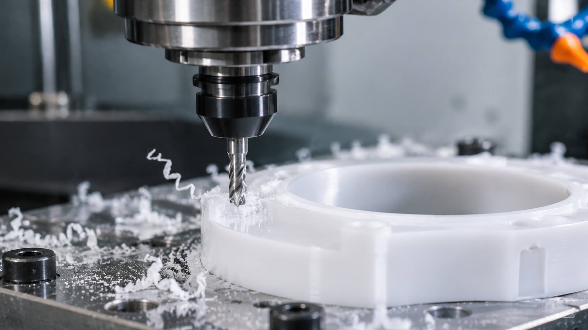
Machining Brass C360 vs. C464: Free-Cutting vs. Naval Brass Machinability, Speeds & Feeds

In precision non-ferrous manufacturing, brass occupies a unique position. Spanning the copper-zinc (Cu-Zn) binary and multi-element metallurgical phase systems, brass alloys deliver an exceptional combination of thermal conductivity, electrical performance, natural lubricity, and corrosion resistance.
However, specifying “brass” on a manufacturing print without distinguishing between free-cutting and naval formulations is a primary source of premature field failures, cost overruns, and severe machining bottlenecks.
The engineering trade-off is stark: C36000 (Free-Cutting Brass) is engineered for maximum subtractive metal-removal rates and represents the global benchmark for machining efficiency. Conversely, C46400 (Naval Brass) is formulated for resistance against marine corrosion and aggressive chloride attack, sacrificing high-speed machinability in the process.
Misapplying these two alloys creates immediate operational risks:
- Utilizing C36000 in seawater or marine immersion environments triggers rapid dezincification—a destructive galvanic corrosion mechanism where zinc is selectively leached from the dual-phase matrix, leaving behind a porous, mechanically weak sponge of copper that fractures under minimal tensile loads.
- Specifying C46400 for high-volume electronic connector pins, fluidic fittings, or instrument shafts without adjusting machining parameters results in broken tooling, tangled stringy chips, tripled machine cycle times, and inflated component costs.
Achieving repeatable tolerances down to ±0.005 mm (±0.0002″) requires an understanding of how micro-alloyed lead and tin govern shear mechanics, chip formation, and cutting forces.
Hardware engineering teams designing mission-critical fluidic, aerospace, or marine hardware can leverage Celerity Precision’s shop-floor infrastructure through our custom copper and brass CNC machining services.
Table of Contents
Metallurgy & Chemical Composition: Why Lead & Tin Dictate Performance
The machinability, shear behavior, and corrosion resistance of brass are dictated by the copper-zinc equilibrium phase diagram, specifically the ratio between the alpha (α) and beta (β) phases, and the presence of micro-alloying elements like lead (Pb) and tin (Sn).
Metallurgical Phase Distribution & Chip Mechanics
Microstructure ComparisonC36000 Free-Cutting Brass
α + β + LeadC46400 Naval Brass
α + β + Tin1. C36000 Free-Cutting Brass: The Physics of Internal Lubrication
C36000 features a duplex α+β microstructure consisting nominally of 60.0% to 63.0% copper, 2.5% to 3.7% lead, and a balance of zinc:
- Alpha (α) Phase: A face-centered cubic (FCC) crystal structure that provides baseline ductility and cold-formability.
- Beta (β) Phase: A body-centered cubic (BCC) crystal structure that forms at higher zinc concentrations, providing high hot-working plasticity, increased hardness, and rigidity.
- The Role of Insoluble Lead Globules: Lead is completely insoluble in the solid copper-zinc matrix. During billet solidification, lead precipitates as sub-micron, spherical droplets dispersed along grain boundaries.
When a cutting tool shears C36000, these dispersed lead globules serve two critical mechanical functions:
- Built-in Stress Concentrators: As plastic shear strain accumulates in the primary shear zone, the lead particles act as micro-void initiation sites. Micro-cracks propagate between adjacent lead droplets, causing the evolving chip to fracture instantly into small, segmented needles rather than continuous ribbons.
- Solid-State Boundary Lubrication: The friction and localized shear heat at the tool-chip interface exceed the low melting point of lead (327°C / 621°F). The lead globules soften and smear across the tool rake face, forming a low-shear-strength boundary layer that reduces friction, lowers cutting forces, and prevents material welding.
2. C46400 Naval Brass: The Physics of Tin and Dezincification Resistance
C46400 possesses a nominal composition of 59.0% to 62.0% copper, 0.5% to 1.0% tin, a maximum of 0.20% lead, and balance zinc:
- Inhibiting Dezincification: When standard duplex brasses contact saline water or brackish solutions, zinc atoms preferentially corrode out of the zinc-rich beta phase, leaving behind a brittle, porous copper network. The addition of approximately 0.75% tin dramatically alters this reaction.
Tin dissolves directly into the alpha and beta phases, forming a thin, adherent, tin-enriched passive oxide film (SnO₂/ZnO) across the surface. This protective passive layer prevents chloride ion (Cl¯) penetration, protecting the alloy from dezincification and cavitation erosion in high-velocity marine environments.
- The Machining Penalty: Because tin is in solid solution, it hardens and strengthens the crystal lattice through solid-solution strengthening. Tensile strength climbs to 480–550 MPa (compared to 400–450 MPa for C36000), while ductility and elongation remain high (30% to 40%).
Crucially, C46400 contains virtually no lead. Lacking micro-void crack initiators, the alloy cannot naturally break chips.
Under subtractive cutting, C46400 shears into tough, continuous, work-hardening ribbons that require substantial cutting power and active chip-breaking geometries.
The 100% Machinability Index Benchmark Explained
In manufacturing metrology, machining efficiency is evaluated using the Machinability Index, a relative benchmark standardized against C36000 Free-Cutting Brass at 100%.
Relative Machinability Index Scale
% of C36000 BaselineWhen an alloy is rated at 100% machinability, it demonstrates:
- Low Specific Cutting Energy (kc≈600 to 750 N/mm², roughly one-fourth that of titanium and one-third that of carbon steel).
- Natural Discontinuous Chip Cleavage requiring zero mechanical chip breakers.
- Long Cutting Tool Life at surface speeds exceeding 1,000 to 1,500 SFM (300 to 450 m/min).
- Clean Surface Finishes (Ra≤0.4μm) achieved straight from the cut without secondary polishing.
By contrast, C46400 Naval Brass carries a machinability rating of only 30%.
Machining C46400 requires cutting parameters and toolpath strategies closer to tough phosphor bronzes or austenitic stainless steels:
- Surface cutting speeds must be reduced by 60% to 70% compared to C36000 to prevent thermal degradation of the tool edge.
- Specific cutting forces jump by more than 80% (kc≈1,200 to 1,400 N/mm²), increasing mechanical loads on toolholders and machine spindles.
- Flank wear rates accelerate due to the absence of sacrificial lead lubrication, demanding advanced PVD coatings to prevent adhesive galling.
Speeds, Feeds & Cutting Parameters
Balancing production cycle times against component quality requires establishing baseline parameters derived from each alloy’s mechanical and metallurgical properties.
| Physical & Mechanical Property | C36000 Free-Cutting | C46400 Naval Brass | Practical CNC Machining Impact |
|---|---|---|---|
| Nominal Chemical Composition | 61.5% Cu, 3.1% Pb, Bal. Zn | 60.0% Cu, 0.75% Sn, 0.1% Pb, Bal. Zn | Lead provides micro-chip breaking; tin provides chloride passivity. |
| Machinability Rating | 100% (The Global Baseline) | 30% | Critical: C464 requires 60% lower speeds, increased spindle torque, and aggressive chip control. |
| Tensile Strength (Yield / Ultimate) | 310 MPa / 450 MPa (45/65 KSI) | 350 MPa / 520 MPa (51/75 KSI) | C464 matrix exerts higher dynamic shear resistance against the tool edge. |
| Hardness (Rockwell B) | 65 – 80 HRB | 75 – 90 HRB | C464 accelerates abrasive flank wear on carbide cutting edges. |
| Elongation at Break (%) | 15% – 25% | 30% – 45% | C464 generates tough, continuous stringer chips that tend to nest around spindles. |
| Thermal Conductivity (at 20°C) | 115 W/(m·K) | 116 W/(m·K) | Both conduct heat well, but C464 generates roughly double the interface friction. |
| Marine Corrosion Resistance | Poor (Prone to Dezincification) | Excellent (Dezincification Inhibited) | Decision Gate: C464 is mandatory for seawater immersion, marine hardware, and subsea valves. |
Validated Cutting Parameters Table: C36000 vs. C46400
The parameter matrix below outlines validated starting parameters across precision turning, high-speed end milling, and drilling operations:
| Operation & Alloy | Tooling Substrate & Coating | Speed (SFM) |
Speed (m/min) |
Chip Load / Feed (FPT / IPR) |
Radial (Ae) | Axial (Ap) |
|---|---|---|---|---|---|---|
| CNC Turning - Roughing C36000 | Polished Carbide (Uncoated / TiN) | 800 – 1,500 | 240 – 450 | 0.15 – 0.35 mm/rev | N/A | 1.50 – 4.00 mm |
| CNC Turning - Finishing C36000 | Polished Carbide (PVD TiN) | 1,000 – 2,000 | 300 – 600 | 0.05 – 0.12 mm/rev | N/A | 0.25 – 0.75 mm |
| CNC Turning - Roughing C46400 | Micro-Grain Carbide (PVD TiCN) | 350 – 600 | 105 – 180 | 0.12 – 0.25 mm/rev | N/A | 1.00 – 2.50 mm |
| CNC Turning - Finishing C46400 | Micro-Grain Carbide (PVD TiCN) | 500 – 850 | 150 – 260 | 0.04 – 0.08 mm/rev | N/A | 0.20 – 0.50 mm |
| High-Speed End Milling C36000 | Sub-micron Solid Carbide (Uncoated) | 800 – 1,800 | 240 – 550 | 0.08 – 0.18 mm/tooth | 0.30 – 0.50 × D | 1.00 – 2.00 × D |
| End Milling - Finishing C36000 | Sub-micron Solid Carbide (Uncoated) | 1,200 – 2,500 | 365 – 760 | 0.02 – 0.06 mm/tooth | 0.05 – 0.10 × D | 0.50 – 1.00 × D |
| High-Speed End Milling C46400 | Sub-micron Solid Carbide (PVD TiCN) | 300 – 600 | 90 – 180 | 0.04 – 0.10 mm/tooth | 0.20 – 0.40 × D | 0.50 – 1.25 × D |
| End Milling - Finishing C46400 | Sub-micron Solid Carbide (PVD TiCN) | 450 – 800 | 135 – 240 | 0.02 – 0.05 mm/tooth | 0.05 – 0.10 × D | 0.25 – 0.75 × D |
| Standard Twist Drilling C36000 | Polished Carbide / HSS-Co | 300 – 600 | 90 – 180 | 0.10 – 0.25 mm/rev | Full Drill D | 1.00 – 3.00 × D (Peck) |
| Standard Twist Drilling C46400 | High-Helix Parabolic Carbide Drill | 150 – 300 | 45 – 90 | 0.06 – 0.15 mm/rev | Full Drill D | 0.50 – 1.00 × D (Peck) |
Tooling Geometry & Chip Control Tactics
C36000 and C46400 require fundamentally opposing cutting tool geometries. Using a tool ground for C464 on C360—or vice versa—leads to immediate dimensional or surface defects.
Comparative Cutter Rake Geometries
Tooling Kinematics MatrixC36000 Free-Cutting Tooling
0° Neutral • Anti-GrabC46400 Naval Brass Tooling
+8° to +12° Positive1. The “Tool Grabbing” Phenomenon in C36000
Because C36000 shears easily, highly positive rake tools (such as standard aluminum-cutting end mills with +15° to +20° rake angles) exhibit an aggressive tendency to “self-feed” or “grab” into the workpiece.
- The Mechanical Fault: As the sharp cutting edge engages, the high positive rake angle pulls the tool into the material along its helix or lead angle, taking a deeper cut than programmed. This causes tool deflection, part pull-out from collets, severe surface chatter, and dimensional bore undersizing.
- The Geometric Solution: Ground tooling for C36000 must feature neutral (0°) or slightly negative (-2° to -4°) rake angles, combined with a primary clearance angle of +6° to +10°. The neutral face acts as a controlled shear plane, preventing self-feeding while allowing the insoluble lead globules to cleave the chips cleanly.
2. High-Shear Tooling for C46400 Naval Brass
Naval brass requires positive cutting geometries to slice through its ductile, tin-reinforced lattice:
- Positive Rake Geometry (+8° to +12°): Positive rake angles reduce specific cutting energy, lower cutting zone temperatures, and guide continuous chips smoothly upward along the flute.
- Ground Chip-Breaker Grooves: Turning inserts and milling cutters for C46400 must feature aggressive, polished 3D chip breakers. The chip breaker curves the ductile ribbon against the unmachined shoulder, snapping it into tight “6” and “9” shapes before it can wrap around the spindle.
- Clearance Angles (+8° to +12°): Adequate flank clearance prevents the elastic recovery of the brass matrix from rubbing against the tool clearance land.
3. Tool Substrates & Advanced PVD Coatings
- Substrate Selection: Use micro-grain solid tungsten carbide (WC-Co) with 6% to 10% cobalt. Sub-micron grains provide the edge retention needed to withstand long production cycles.
- PVD TiN (Titanium Nitride): The classic gold PVD coating remains effective for C36000, providing an inert barrier that prevents micro-welding at elevated feeds.
- PVD TiCN (Titanium Carbonitride): For C46400, TiCN is the preferred coating. Its carbon content lowers the sliding coefficient of friction (μ≈0.35 against non-ferrous metals), preventing adhesive galling and built-up edge (BUE) formation during dry or semi-dry cutting.
- Avoid Polycrystalline Diamond (PCD) for Leaded C36000: PCD is cost-prohibitive and unnecessary for free-cutting brass; sharp, polished uncoated carbide delivers equivalent finishes (Ra<0.2μm) at a fraction of the tooling cost.
Coolant Discipline & Preventing Surface Tarnishing
Brass possesses high natural thermal conductivity (∼115 W/(m⋅K)). In high-speed machining, cutting heat dissipates rapidly into the chips and the surrounding coolant.
However, brass is chemically reactive, and improper cutting fluids will trigger severe surface discoloration, water staining, and corrosion.
Mechanics of Brass Surface Tarnishing
Chemical Oxidation Defect1. Coolant Selection: C36000 vs. C46400
- C36000 (Dry Machining & Cold Air): Due to its low specific cutting resistance and self-lubricating lead content, C36000 is suited for dry cutting or vortex-cooled cold air (-5°C to 0°C). Dry cutting eliminates fluid purchase, simplifies chip recycling (dry brass turnings command a premium at recyclers), and prevents chemical staining. When drilling deep micro-holes, use neat, non-staining mineral cutting oils.
- C46400 (Lubricated Emulsions): C46400 generates high frictional heat that requires fluid flood cooling. Use chlorine-free and sulfur-free water-soluble synthetic or semi-synthetic emulsions mixed at 8% to 10% concentration. Active sulfur or chlorine additives chemically attack brass, forming dark brown or black copper sulfide (Cu₂S) stains within hours.
2. Coolant pH Control: The 8.5 to 9.2 Window
Maintaining cutting fluid chemistry is critical:
- Acidic Degradation (pH < 8.2): As metalworking fluids age, bacterial growth generates acidic byproducts. Acidic coolant leaches zinc and copper from the surface, creating green copper carbonate Cu₂CO₃) spots and dark water stains that cannot be wiped clean.
- Alkaline Degradation (pH > 9.5): Overly alkaline fluids dissolve zinc, etching precision-turned surfaces and leaving dull gray oxide films.
- Quality Mandate: Monitor coolant sumps weekly using calibrated digital pH meters. Maintain pH strictly between 8.5 and 9.2 using non-staining buffers.
3. Post-Machining Ultrasonic Cleaning & Passivation
To guarantee that components arrive with uniform, bright metallic finishes:
- Ultrasonic Degreasing: Immediately following CNC machining, submerge brass parts in ultrasonic baths containing mild, neutral-pH non-ionic surfactants heated to 50°C to 60°C. Ultrasonic cavitation strips away embedded chip fragments, micro-swarf, and oil films from blind tapped holes.
- Deionized Water Rinse: Rinse parts twice in pure deionized (DI) water. Tap water contains dissolved chlorides and calcium that leave mineral deposit rings upon evaporation.
- Rapid Forced-Air Dehydration: Dry components in centrifugal drying barrels or heated forced-air convection tunnels at 80°C to 100°C. Never allow damp brass parts to air-dry in open shop air.
- Chemical Passivation / Bright Dipping: For optical, medical, or marine applications, specify a chemical passivation treatment (such as a citric-acid-based dip or benzotriazole / BTA immersion). Benzotriazole forms a transparent, mono-molecular polymer complex with copper atoms ([Cu(BTA)]ₙ), creating a barrier against atmospheric oxidation, fingerprint acid staining, and humidity.
High-Speed Production on Celerity Shop-Floor Equipment
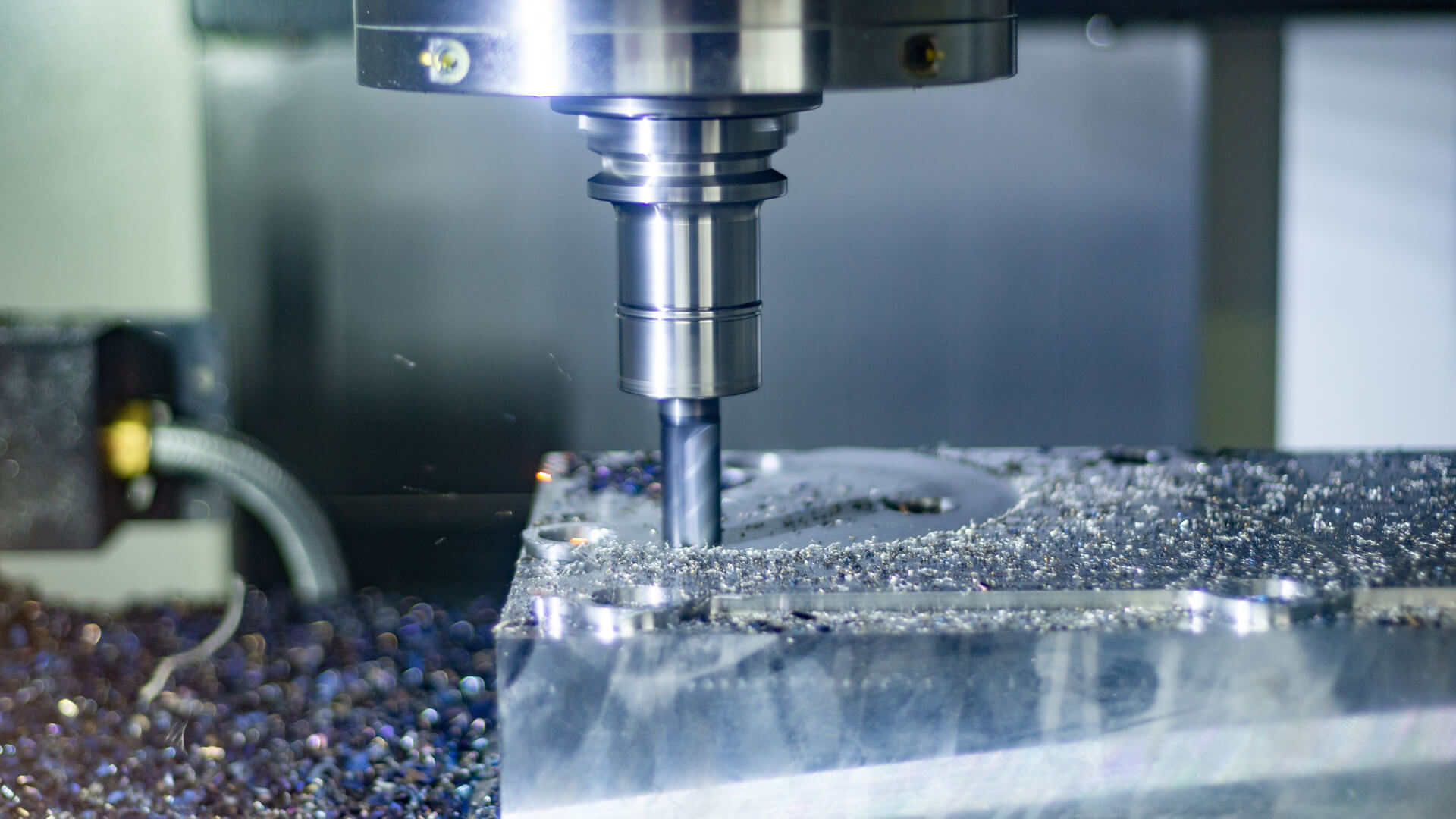
Machining brass efficiently requires high spindle RPM, rapid axis acceleration, and synchronized chip clearing to maximize output.
At Celerity Precision, brass production is distributed across dedicated machining platforms:
1. High-Speed Production Kinematics (Fanuc Robodrill & Makino a40)
For high-volume fluidic fittings, electronic terminal blocks, and marine sensor housings:
- Dynamic Spindle Acceleration: Our Fanuc Robodrill platforms feature high-torque 15,000 RPM spindles and 1.5G axis acceleration rates. Rapid acceleration allows small-diameter end mills and drills to maintain high cutting speeds in pocket corners without dwelling, maximizing throughput.
- Horizontal Evacuation Stability: For multi-sided naval brass valve bodies, our Makino a40 horizontal machining centers utilize rigid stepped-column castings and 500 mm dual-pallet changers. The horizontal spindle orientation allows heavy chip showers from C46400 roughing to fall under gravity directly into the chip conveyor, preventing the re-cutting of work-hardened chips.
2. Burr-Free Micro-Milling & Micro-Holes (Beijing Jingdiao JDGR200T)
Machining miniature RF coaxial housings, micro-fluidic manifolds, and electronic pin arrays with hole diameters below 0.50 mm:
- 4,000 RPM Direct-Drive Spindles: Our Beijing Jingdiao JDGR200T high-speed centers feature high-frequency electro-spindles with dynamic radial runout under .001 mm (0.00004″).
- Burr-Free Micro-Machining: Operating at 24,000 RPM provides the high surface speed required for micro-cutters (0.2 mm to 1.0 mm diameter). High-speed shearing slices cleanly through brass fibers, suppressing exit burr formation and eliminating manual bench deburring that risks rounding micro-sealing lands.
To review our complete production floor capabilities, inspect our precision CNC turning services and custom CNC milling facilities.
Quality Assurance & RoHS / REACH Compliance
Meeting international regulatory requirements is essential when machining brass for export, medical instrumentation, or municipal water distribution:
1. Zeiss CMM Dimensional Inspection
Dimensional verification of tight-tolerance sealing bores, thread pitch diameters, and multi-axis datums is conducted inside Celerity Precision’s climate-controlled quality assurance laboratory, maintained at 20°C ± 1°C (68°F ± 1.8°F).
- Thermal Expansion Stabilization: Both C36000 and C46400 exhibit moderate thermal expansion (≈20.5×10⁻⁶/K). High-speed production parts rest inside the metrology lab for 2 to 4 hours to normalize to 20°C before final measurement.
- Zeiss Scanning Probes: Spatial dimensional verification is performed on our bridge-type Zeiss CMM. Scanning probes map true-position hole locations, stepped bore concentricities, and sealing-face flatnesses down to ±0.005 mm (±0.0002″).
- Optical Vision Metrology: Miniature thread profiles, external grooves, and deburred edge chamfers are inspected using automated high-resolution vision measuring machines (VMM), preventing probe stylus deflection on delicate features.
2. Raw Material Lot Verification via XRF Spectroscopy & RoHS Compliance
A critical compliance concern in the brass supply chain is Lead (Pb) Content Verification:
XRF Spectroscopic Compliance Screening Pipeline
RoHS & Lead-Free Metallurgy QA- RoHS Directive Exemption 6(c): The European Union RoHS Directive restricts lead in electronic and electrical equipment, but provides an exemption (Exemption 6(c)) allowing up to 4.0% lead by weight in copper alloys, permitting standard C36000.
- Drinking Water Mandates (California AB 1953 & US Safe Drinking Water Act): For potable water distribution and food-contact devices, the law mandates lead-free brass (wetted surface lead content <0.25%). For these applications, Celerity Precision routes production through certified lead-free brasses (such as C27450 or silicon-brass C69300 / Eco Brass).
- On-Site XRF Verification: Every incoming raw material lot is scanned with our on-site X-Ray Fluorescence (XRF) Spectrometer / Analyzer. The XRF verifies:
- C36000: Confirms copper (60.0%–63.0%), lead (2.5%–3.7%), and zinc balance, verifying compliance with ASTM B16 and RoHS Exemption 6(c).
- C46400: Confirms copper (59.0%–62.0%), tin (0.5%–1.0%), and verifies lead is below 0.20%, guaranteeing ASTM B21 marine specifications.
DFM Rules for Precision Brass Components
Disciplined Design for Manufacturability (DFM) lowers unit costs, shortens machine cycle times, and improves the mechanical integrity of precision brass parts:
1. Specify Roll Tapping (Form Tapping) Over Cut Tapping for Internal Threads
Cutting internal threads in ductile non-ferrous metals like C46400 or C36000 using traditional fluted cutting taps generates fine swarf that binds in blind hole bottoms, risking tap breakage.
- DFM Rule: Design internal threads to accommodate roll forming taps (fluteless cold-forming taps). Roll tapping plastically deforms the brass fibers along the thread profile rather than severing them:
- Eliminates cutting chips entirely, making blind-hole threading reliable.
- Increases thread shear pullout strength by 20% to 30% due to grain-flow work hardening.
- Extends tapping tool life by up to 500%.
- Specify proper pre-tap core-drill diameters on drawings (roll taps require a larger pilot hole than cutting taps).
2. Avoid Deep, Unsupported Thin Walls (Maintain Wall Thickness ≥ 0.75 mm)
While brass is stiffer than engineering plastics (elastic modulus ~100 to 110 GPa), thin vertical walls (<0.5 mm) deflect under cutting forces during high-speed milling.
- DFM Rule: Maintain minimum structural wall thicknesses ≥0.75 mm (0.030″), and ideally ≥1.00 mm. If thin fins are functional requirements (such as RF shields or heat-dissipation fins), incorporate supporting ribs, or allow a 1° to 2° draft angle along the wall base to resist cutter deflection and chatter.
3. Incorporate Edge Chamfers to Eliminate Deburring Operations
Because of its ductility, C46400 produces exit burrs where the cutter sweeps off an edge. Hand deburring adds labor and risks inconsistent corner breaks.
- DFM Rule: Design 0.20 mm to 0.50 mm×45° chamfers on all exposed part edges directly in the 3D CAD model. Modeled chamfers allow CNC programmers to deploy automated chamfer-milling toolpaths, deburring the component on the machine tool and shipping parts clean straight from the fixture.
4. Provide Undercuts and Reliefs on Turned Shoulders
When turning stepped shafts or external threads, running a threading tool or turning insert hard into a 90-degree shoulder accelerates corner wear and creates localized stress concentrations.
- DFM Rule: Incorporate standard thread relief grooves (undercuts per DIN 76 or ANSI B47.1) between threaded sections and adjacent shoulders. For precision bearing journals, specify a minimum transition radius of R≥0.40 mm to prevent stress concentration under cyclic bending loads.
Precision Brass Component Sourcing & Production
Machining brass to tight tolerances requires moving past trial-and-error setups. Repeatable production demands matching alloy metallurgy with appropriate tool geometries: using neutral-rake cutters for free-cutting C36000 to prevent self-feeding, running positive-rake coated carbide with active chip breakers for naval C46400, strictly controlling coolant pH to prevent surface tarnishing, and verifying dimensions with low-force Zeiss CMMs.
Whether your assembly requires high-volume turned electrical contacts produced on our precision CNC turning services cells or complex, multi-axis marine manifold blocks milled via our custom CNC milling centers, Celerity Precision delivers repeatable, tight-tolerance components backed by material certifications and inspection reports.
Request a Comprehensive DFM Analysis and Precision Brass Quote
Submit your 3D CAD models (STEP, IGS) and 2D engineering drawings to our application engineering team. We will deliver an engineering-grade manufacturability review within 24 hours, evaluating alloy suitability (C360 vs. C464 vs. lead-free alternatives), roll-threading feasibility, tolerance stack-up analysis, and transparent factory-direct pricing.
- Strict Non-Disclosure Agreement (NDA) Protection
- 4-Hour Engineering DFM & Quotation Turnaround
- Zeiss CMM Dimensional Inspection & XRF Chemical Certification
Upload your CAD drawings via our contact page to begin your project review with our engineering team.

CP Engineering Team
Authored and peer-reviewed by the Senior Engineering and Metrology Team at Celerity Precision. Backed by German 5-axis CNC machining centers, high-speed micro-milling platforms, and a climate-controlled Zeiss CMM inspection lab, our team delivers deep DFM insights, material machinability guides, and precision manufacturing solutions for aerospace, medical, and semiconductor developers worldwide.