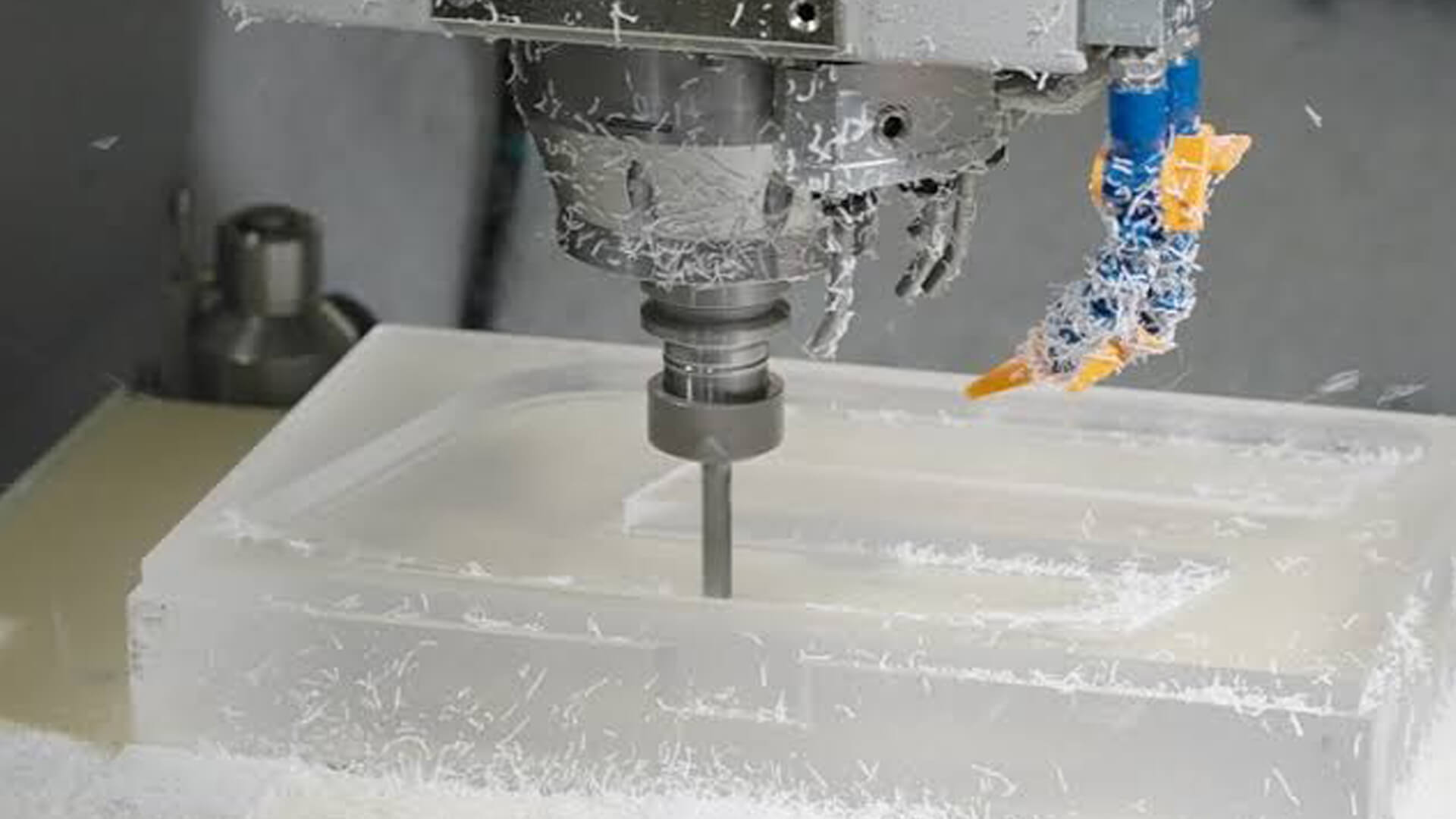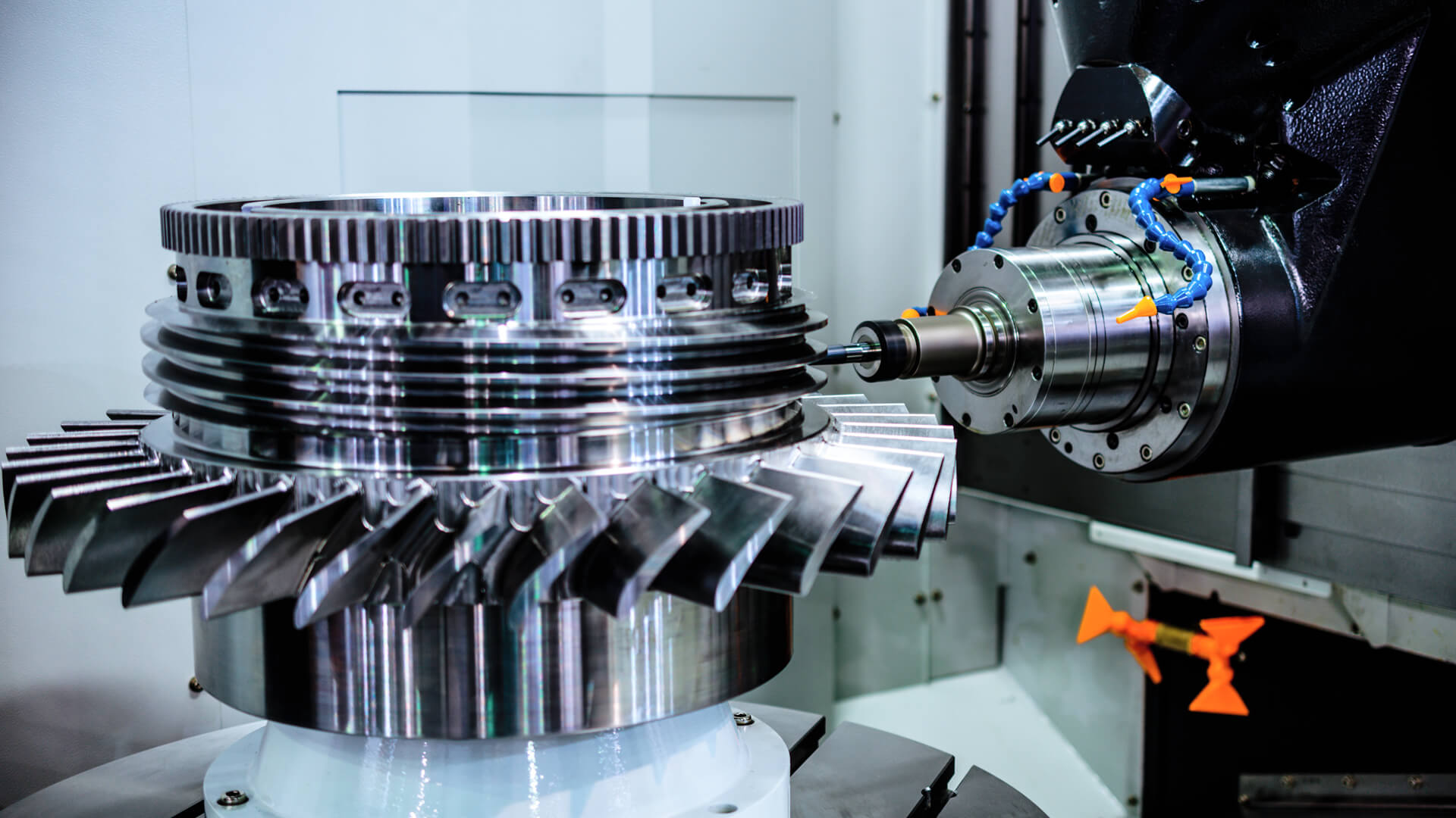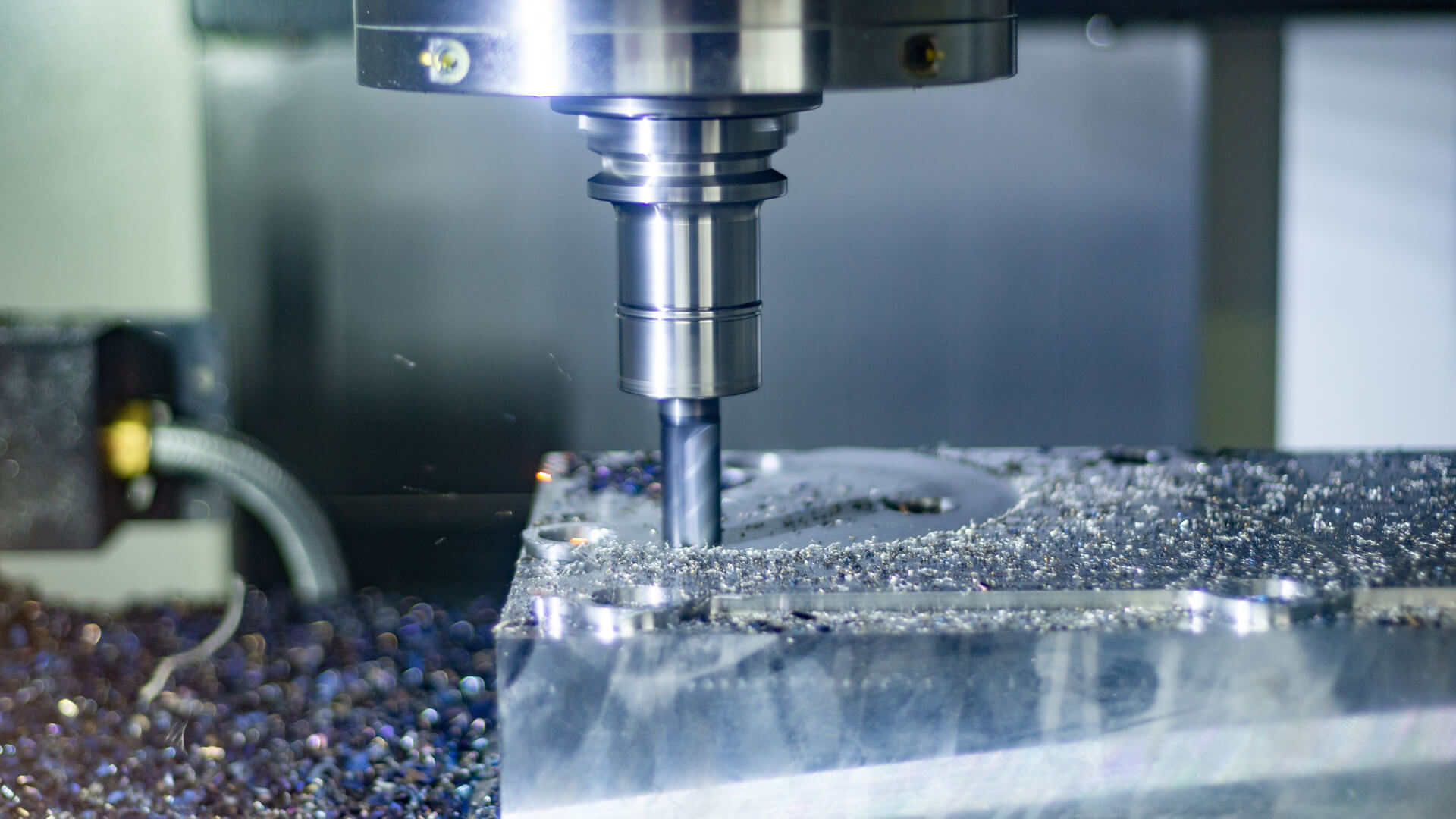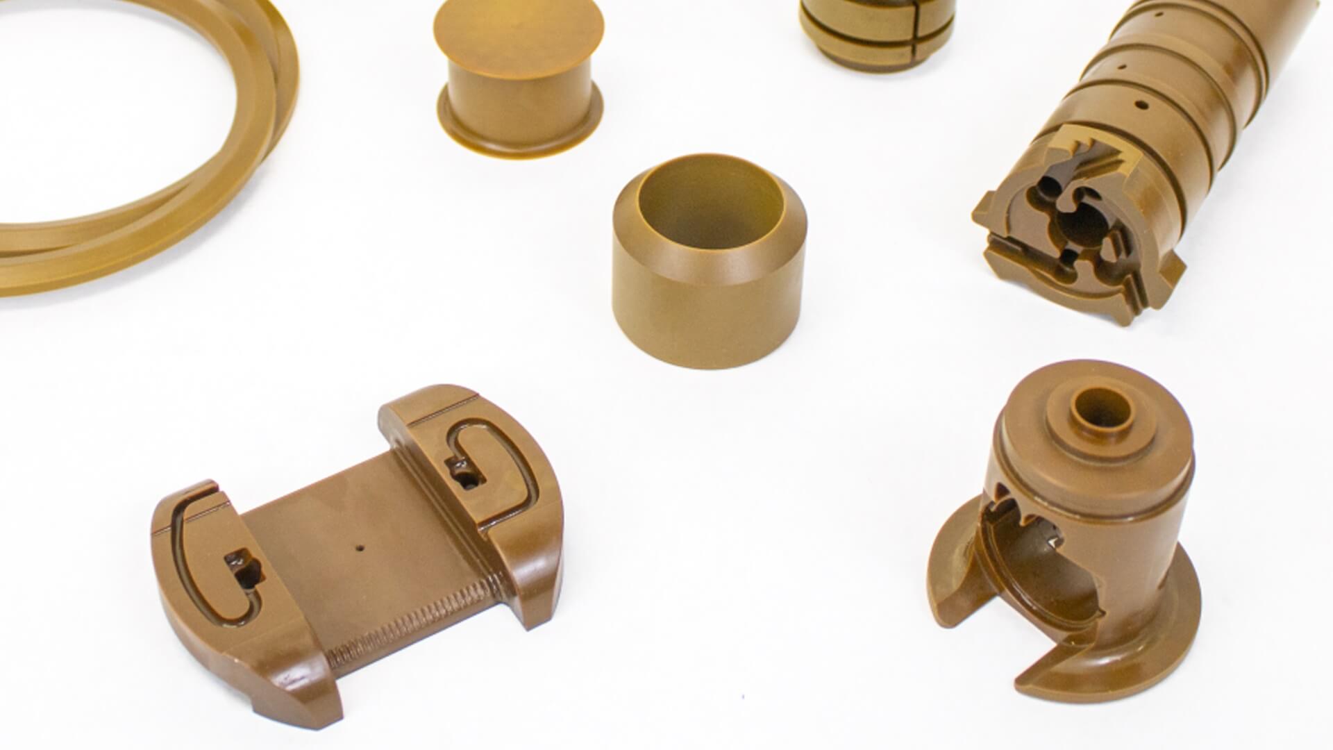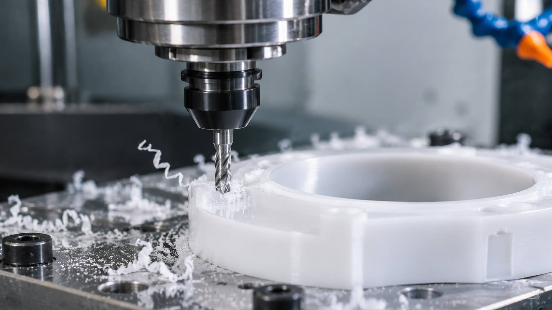
Precision CNC Machining Torlon PAI: Cutting Speeds, Tooling, Moisture Control & Post-Curing Guidelines

Polyamide-imide (PAI), commercially known under the trade name Torlon (developed by Solvay), represents the absolute peak of commercially available, melt-processable high-performance engineering thermoplastics. Combining the mechanical rigidity and high-temperature performance of aromatic polyimides with the melt-processing characteristics of polyamides, Torlon delivers mechanical, thermal, and electrical performance in environments where PEEK, Ultem (PEI), and polybenzimidazole (PBI) reach their physical limits.
With an exceptionally high glass transition temperature (Tg=275°C/527°F) and continuous service capability up to 260°C (500°F), Torlon PAI maintains structural integrity under extreme mechanical stress.
At 200°C (392°F), unfilled Torlon retains a tensile strength exceeding 100 MPa—higher than the room-temperature strength of many standard engineering polymers like polyacetal (POM) and nylon (PA66).
Its room-temperature tensile strength reaches 150 to 220 MPa (depending on filler reinforcement), accompanied by an exceptionally high compressive strength (up to 250 MPa) and a thermal expansion coefficient closely matching structural metals like stainless steel and titanium.
These properties make Torlon indispensable for mission-critical components:
- Semiconductor IC Test Sockets & Wafer Processing Fixtures: Micro-drilled array plates with thousands of blind and through-holes down to Φ0.20 mm that require zero burrs, high dielectric insulation, and tight dimensional stability across continuous thermal cycling.
- Aerospace & Cryogenic Fasteners: Structural nuts, bushings, and standoffs that endure thermal shock from -196°C to +260°C without brittle micro-cracking.
- High-Pressure Hydraulic Fluid Control: Valve plates, wear rings, and downhole completion seals operating under continuous high PV (pressure-velocity) loads in aggressive hydrocarbon environments.
However, subtractive CNC machining of Torlon PAI is considered one of the most challenging operations in precision manufacturing.
The material is hygroscopic, absorbing atmospheric moisture that can vaporize into destructive steam blisters during machining or thermal cycles.
Furthermore, glass- and carbon-filled grades rapidly dull cutting tools, and components must undergo a multi-day post-curing thermal cycle to achieve their full theoretical strength.
Navigating these challenges requires strict parameter discipline, specialized cutter geometries, structured stress-relief workflows, and low-force metrology. Hardware development teams looking for certified aerospace, semiconductor, or medical components can partner with Celerity Precision through our custom PAI Torlon CNC machining services.
Table of Contents
Torlon Grade Selection & Physical Comparison
Torlon is formulated in three primary extruded and injection-molded grades. Selecting the correct grade dictates tooling selection, post-curing cycles, and machinability parameters:
1. Torlon 4203 (Extruded) / 4000T (Molded) – Electrical & Bearing Grade (Unfilled)
Torlon 4203 is an unreinforced, pigmented (yellow-ochre) grade offering the highest elongation at break (up to 15% post-cure) and maximum impact toughness among the PAI family. Because it contains no abrasive fillers, it exhibits high dielectric strength and electrical insulation across broad frequency ranges.
It is the industry-standard resin for semiconductor test sockets, electrical insulators, high-load valve seats, and cryogenic structural components.
From a machining perspective, 4203 is ductile, requiring razor-sharp cutting edges to prevent gummy burr formation and thermal gumming.
2. Torlon 4301 – Wear & Friction Grade (12% Graphite + 3% PTFE)
Torlon 4301 incorporates 12% graphite powder and 3% PTFE (polytetrafluoroethylene) lubricating additives into the PAI matrix. This formulation delivers an extremely low dynamic coefficient of friction, high thermal conductivity, and high PV limits under unlubricated boundary friction conditions.
It is widely specified for non-lubricated aerospace bushings, thrust washers, rotating pump vanes, and high-speed mechanical seals.
Machinability is excellent; the solid lubricants promote natural chip cleavage, generating powdery, discontinuous chips, though the graphite dust requires dedicated vacuum extraction.
3. Torlon 5030 – Structural Grade (30% Glass-Fiber Reinforced)
Torlon 5030 is reinforced with 30% chopped micro-glass fibers, multiplying its flexural modulus to over 14,000 MPa (comparable to structural magnesium and cast aluminum) while cutting its thermal expansion coefficient by more than half (down to 16×10⁻⁶/K, closely matching structural carbon steel).
It is specified for satellite optical brackets, turbine blade retaining rings, high-pressure piston rings, and aerospace structural housings.
From a machining standpoint, Torlon 5030 is extremely abrasive. Standard tungsten carbide cutting tools experience catastrophic flank wear and rounded cutting edges within minutes of cut engagement.
| Physical & Mechanical Property | Torlon 4203 Unfilled | Torlon 4301 Bearing | Torlon 5030 30% Glass | PEEK 450G Ref |
|---|---|---|---|---|
| Tensile Strength at Yield (23°C) | 150 – 190 MPa (22–27 KSI) | 115 – 145 MPa (17–21 KSI) | 200 – 230 MPa (29–33 KSI) | 100 – 105 MPa (14.5–15 KSI) |
| Tensile Strength at High Heat (200°C) | 100 – 115 MPa (Retains 65%) | 75 – 90 MPa | 135 – 155 MPa (Extreme) | 15 – 25 MPa (Plasticized) |
| Flexural Modulus (23°C) | 4,500 – 5,000 MPa | 5,500 – 6,500 MPa | 13,500 – 15,000 MPa | 3,800 – 4,100 MPa |
| Coefficient of Thermal Expansion (CTE) | 31 × 10⁻⁶ / K | 25 × 10⁻⁶ / K | 16 × 10⁻⁶ / K (Matches Steel) | 47 × 10⁻⁶ / K |
| Glass Transition Temp (Tg) | 275°C (527°F) | 275°C (527°F) | 275°C (527°F) | 143°C (289°F) |
| Max Continuous Service Temperature | 260°C (500°F) | 260°C (500°F) | 260°C (500°F) | 240°C (464°F) |
| Primary Industrial Applications | Semiconductor Sockets, Isolators | Bushings, Sliders, Thrust Washers | Aerospace Brackets, Standoffs | Chemical Manifolds, Valves |
The Moisture Paradox & Pre-Machining Conditioning
The primary cause of dimensional non-conformance and surface failure in Torlon components is its hygroscopic nature.
Unlike PEEK or PTFE, which absorb virtually zero moisture, the amide groups within the PAI polymer chain naturally form hydrogen bonds with atmospheric water vapor:
- Equilibrium Moisture Absorption: Exposed to ambient shop air (50% Relative Humidity at 23°C), raw Torlon bar stock absorbs between 0.3% and 0.5% water by weight within 24 to 48 hours, climbing to over 2.0% to 2.5% at complete saturation.
- The Dimensional Swelling Penalty: As water molecules enter the amorphous matrix, they force polymer chains apart, causing isotropic volumetric expansion. For every 1.0% increase in absorbed moisture content, Torlon expands by approximately 0.05% to 0.08% linearly. On a 100 mm semiconductor test socket plate, moisture absorption can introduce a dimensional drift of 0.050 mm to 0.080 mm—consuming the entire tolerance band of a high-precision part.
The Destructive “Steam Blistering” Mechanism
Hygroscopic Thermal Defect- The “Steam Blistering” Hazard: If a moisture-saturated Torlon blank is machined with aggressive, heat-generating cuts, or placed into an oven for post-curing without preliminary dehydration, the water trapped within the dense polymer core flashes into superheated steam.
Because PAI exhibits low gas permeability, this steam cannot diffuse out safely.
The localized internal vapor pressure rapidly exceeds the tensile yield strength of the hot polymer, causing sub-surface steam blistering, internal delamination, micro-void voids, and catastrophic part cracking.
The Pre-Machining Dehydration Protocol
To stabilize dimensions and eliminate steam blistering, all raw Torlon billets, extruded plates, and bar stock must undergo a mandatory pre-machining drying cycle:
- Place raw stock into an air-circulating, desiccant-dehumidified industrial oven.
- Ramp temperature at +15°C/hr up to 120°C (248°F).
- Soak at 120°C for a minimum of 4 hours per 12 mm (0.50″) of cross-sectional thickness to drive out all absorbed moisture.
- Cool slowly to room temperature inside the oven.
- Transfer stock immediately to the machine tool, or store it in sealed desiccant dry-cabinets (Relative Humidity < 5%) if machining is delayed by more than 2 hours.
Speeds, Feeds & Cutting Parameters
Machining Torlon requires balancing linear surface cutting speed against positive mechanical feed per tooth.
Because Torlon has low thermal conductivity (0.26 to0.30 W/(m⋅K)), cutting heat does not conduct away through the polymer core. The heat accumulates rapidly at the tool-chip interface.
Running spindle speeds too high with inadequate feed causes the tool flutes to burnish and rub, leading to localized thermal softening, resin smearing, dimensional distortion, and heavy burrs.
Conversely, running feeds too heavy without adequate cutter support can fracture the brittle, unlubricated edges of structural Torlon 5030.
The parameters below distinguish between unfilled/bearing grades (4203/4301) and glass-reinforced structural Torlon 5030:
| Operation & Grade | Tooling Substrate & Coating | Speed (SFM) |
Speed (m/min) |
Chip Load / Feed (FPT / IPR) |
Radial (Ae) | Axial (Ap) |
|---|---|---|---|---|---|---|
| End Milling - Roughing 4203 / 4301 | Sub-micron Solid Carbide (Uncoated) | 300 – 500 | 90 – 150 | 0.05 – 0.10 mm/tooth | 0.30 – 0.50 × D | 0.75 – 1.25 × D |
| End Milling - Finishing 4203 / 4301 | Polished Solid Carbide (DLC / Uncoated) | 450 – 750 | 135 – 230 | 0.02 – 0.05 mm/tooth | 0.05 – 0.10 × D | 0.25 – 0.75 × D |
| End Milling - Roughing 5030 (GF30) | Polycrystalline Diamond (PCD) / CVD | 200 – 350 | 60 – 105 | 0.03 – 0.08 mm/tooth | 0.20 – 0.40 × D | 0.50 – 1.00 × D |
| End Milling - Finishing 5030 (GF30) | Polycrystalline Diamond (PCD) | 300 – 500 | 90 – 150 | 0.015 – 0.04 mm/tooth | 0.04 – 0.08 × D | 0.20 – 0.50 × D |
| CNC Turning - Roughing 4203 / 4301 | Polished Carbide (CCGT/DCGT) | 350 – 600 | 105 – 180 | 0.10 – 0.25 mm/rev | N/A | 1.00 – 2.50 mm |
| CNC Turning - Finishing 4203 / 4301 | Polished Carbide (DCGT / VCGT) | 500 – 800 | 150 – 240 | 0.03 – 0.08 mm/rev | N/A | 0.20 – 0.50 mm |
| CNC Turning - Roughing 5030 (GF30) | PCD Insert (Fine Grain 2 µm) | 250 – 400 | 75 – 120 | 0.08 – 0.18 mm/rev | N/A | 0.75 – 2.00 mm |
| CNC Turning - Finishing 5030 (GF30) | PCD Insert (Sub-micron Diamond) | 350 – 600 | 105 – 180 | 0.025 – 0.06 mm/rev | N/A | 0.15 – 0.40 mm |
| Standard Twist Drilling 4203 / 4301 | Polished Solid Carbide (Parabolic) | 120 – 220 | 36 – 65 | 0.04 – 0.10 mm/rev | Full Drill D | 0.50 – 1.00 × D (Peck) |
| Micro-Drilling (Φ<0.5mm) IC Sockets | Ultra-Micro-Grain Carbide Drill | 150 – 250 | 45 – 75 | 0.003 – 0.008 mm/rev | Full Drill D | 0.10 – 0.25 × D (Peck) |
| Standard Twist Drilling 5030 (GF30) | Diamond-Coated Carbide / PCD Drill | 100 – 180 | 30 – 55 | 0.03 – 0.07 mm/rev | Full Drill D | 0.25 – 0.50 × D (Peck) |
Tooling Physics: Diamond (PCD) vs. Micro-Grain Carbide
The mechanical properties of Torlon require matching tool substrates to the specific resin grade:
Tooling Selection Strategy for Torlon PAI
Cutter Substrate & KinematicsTorlon 4203 / 4301 (Unfilled & Bearing)
Carbide ProtocolTorlon 5030 (30% Glass Reinforced)
PCD Diamond Mandate1. The Severe Abrasiveness of Torlon 5030
Chopped glass fibers in Torlon 5030 act as continuous abrasives against the cutting edge.
When cutting 5030 with standard solid carbide tools, the abrasive glass particles wear away the softer cobalt binder matrix, rounding the cutting edge radius (rβ) past 15 µm within minutes.
Once the edge is dull, cutting forces and friction spike. The dull tool pushes and tears the glass fibers out of the PAI matrix rather than shearing them, producing severe sub-surface micro-voids, rough surface finishes (Ra>1.6μm), and dimensional drift.
- The PCD Mandate: When milling or turning Torlon 5030 across production batches, Polycrystalline Diamond (PCD) tooling is mandatory. PCD features a micro-hardness exceeding 8,000 HV (compared to ~1,600 to 1,800 HV for tungsten carbide).
A fine-grained PCD cutting tool (diamond grain size 2 µm to 5 µm) maintains a sharp cutting edge up to 30 to 50 times longer than carbide in 30% glass-filled PAI, holding dimensional tolerances under ±0.005 mm across hundreds of components.
2. Cutter Geometries for Unfilled Torlon 4203 & 4301
Unfilled Torlon 4203 requires high-shear geometry to slice cleanly through its ductile polymer chains:
- Razor-Sharp Cutting Edges (rβ<4μm): Use ultra-fine sub-micron grain solid carbide ground to a razor edge. Avoid standard physical vapor deposition (PVD) coatings like TiAlN or AlCrN; the coating deposition process naturally rounds the cutting edge to a radius of 10–15 µm. Thick coatings convert clean shearing action into compressive plowing, generating localized heat that smears the cut face.
- Mirror-Polished Flutes (Ra<0.05μm): Flute surfaces must feature an optical mirror polish. Because PAI exhibits high mechanical friction under heat, polished flutes allow chips to slide freely up the tool without sticking.
- Positive Rake & High Relief Angles:
- Primary Rake Angle: Specify +8° to +12° positive rake to slice through polymer chains cleanly and lift chips away from the cut.
- Primary Relief Angle: Specify +10° to +15° clearance to prevent the workpiece from elastically snapping back against the tool flank.
3. Holemaking & Micro-Drilling (IC Test Sockets)
Drilling thousands of Φ0.20 mm to 0.50 mm pin holes in Torlon 4203 semiconductor test boards is challenging:
- Drill Geometry: Use micro-grain solid carbide parabolic-flute drills with a 130° to 140° point angle and high helix angle (30° to 35°) to eject powdery chips out of deep holes.
- Kinematic Cycle: Use high-frequency micro-peck drilling cycles. Peck depths must not exceed 0.10×D to 0.25×D in micro-drilling. The drill must fully clear the hole on each peck, supported by a directed clean-air blast to clear chips and prevent chip re-packing, which causes thermal drill seizure and micro-cracking around the hole rim.
The Critical Post-Curing Heat Treatment Process
The defining metallurgical feature of Torlon PAI is that machined parts are not fully cured straight off the machine tool.
During the commercial manufacturing of raw Torlon resin and extruded shapes, the polymer is only partially imidized (typically achieving 60% to 75% of its potential molecular cross-linking).
This partial curing is intentional: if the resin were fully imidized at the material plant, it would become completely infusible and intractable, making it impossible to extrude into defect-free rods and slabs.
Chemical Imidization Mechanism in Torlon PAI
Polymerization PhysicsThe post-curing process drives a solid-state condensation polymerization reaction:
- Chemical Imidization: The thermal cycle converts residual unreacted polyamic acid groups into rigid polyimide rings while driving off condensation reaction byproducts (principally trace water).
- Molecular Weight Increase: Polymer chain lengths extend, and molecular chains align and cross-link through hydrogen bonding.
- Mechanical & Thermal Property Gains: A fully post-cured Torlon part demonstrates:
- Tensile and compressive strength increase by 30% to 40%.
- Elongation at break and impact toughness nearly double.
- Dynamic wear resistance and PV limits increase by over 300%.
- Heat deflection temperature under load (HDT) rises to its maximum rating of 278°C (532°F).
The Multi-Stage Post-Curing Thermal Schedule
Post-curing cannot be rushed. If the temperature is raised too quickly, residual reaction water will vaporize into internal steam blisters, destroying the part.
The thermal cycle must follow a programmed step-ramp schedule inside an air-circulating oven over 7 to 11 days:
| Post-Curing Phase | Temperature Target & Dwell | Thermal Ramp-Up Rate | Soak Duration | Physical & Chemical Objective |
|---|---|---|---|---|
| Stage 1: Dehydration & Soft Cure | 150°C (302°F) | +10°C / hr from room temp | 24 Hours | Drives off free absorbed moisture safely; initiates low-temp solid-state imidization. |
| Stage 2: Low-Temp Imidization | 190°C (374°F) | +5°C / hr from 150°C | 24 Hours | Converts initial polyamic acid groups; prevents sudden volumetric thermal shock. |
| Stage 3: Intermediate Chain Extension | 205°C (401°F) | +5°C / hr from 190°C | 24 Hours | Accelerates chain extension; condensation water diffuses out safely through the core. |
| Stage 4: High-Temp Cross-Linking | 230°C (446°F) | +5°C / hr from 205°C | 24 Hours | Cross-linking reaction intensifies; flexural modulus and hot mechanical strength climb rapidly. |
| Stage 5: Peak Imidization Soak | 250°C – 260°C (482°F–500°F) | +5°C / hr from 230°C | 48 to 96 Hours (1) | Final Conversion: Complete closure into polyimide rings; unlocks maximum dynamic wear resistance and 200+ MPa tensile strength. |
| Stage 6: Controlled Cooldown | Down to < 50°C (122°F) | -5°C to -8°C / hr max | 36 to 48 Hours | Strictly slow cooling inside closed oven to eliminate thermal shock, freezing stresses, and geometric warpage. |
Managing Post-Curing Volumetric Shrinkage
As Torlon completes its chemical imidization, the molecular chains pack closer together, resulting in isotropic volumetric shrinkage of approximately 0.2% to 0.5% linearly.
To hold tolerances down to ±0.005 mm (±0.0002″):
- Rough-machine the component, leaving 0.35 mm to 0.50 mm (0.014″ to 0.020″) of finish stock allowance on critical datums and bore diameters.
- Subject the semi-machined component to the complete 7-to-11 day post-curing cycle. The bulk volumetric shrinkage occurs during this intermediate heat treatment.
- Return the fully cured, stabilized component to the CNC machine tool. Execute light, razor-sharp finish skim passes (ap≤0.10 mm, sharp PCD or polished carbide, copious cold air) to bring dimensions to print.
Coolant Strategies & High-Speed Machine Kinematics
Due to Torlon’s low thermal conductivity and sensitivity to aggressive solvents, cooling and cleaning require strict discipline:
- Dry Machining with Vortex Cold-Air Guns (-10°C to 0°C): This is the benchmark method for Torlon 4203 and 4301. Pressurized cold air cools the tool-chip interface, chills ductile chips to prevent burring, and evacuates abrasive particles without chemical contamination.
- Water-Soluble Synthetic Coolants: If liquid flood cooling is required for deep-pocket roughing or high-speed milling in Torlon 5030, use clean, oil-free synthetic coolants. The coolant must be completely free of active sulfur, chlorine, and aromatic mineral oils.
- Solvent-Free Cleaning Mandate: Never clean machined Torlon components with acetone, MEK, or chlorinated degreasers. Clean components in ultrasonic baths containing warm deionized water and neutral-pH non-ionic surfactants, followed by an immediate pure DI water rinse and oven drying at 80°C.
Precision Shop-Floor Infrastructure at Celerity
At Celerity Precision, we route complex Torlon components across specialized machine platforms:
1. Burr-Free Micro-Milling (Beijing Jingdiao JDGR200T)
Semiconductor IC test sockets and micro-fluidic manifolds require high spindle RPM, ultra-low runout, and micro-feed precision:
- 4,000 RPM Direct-Drive Spindles: Our Beijing Jingdiao JDGR200T 5-axis high-speed centers feature high-frequency electro-spindles with dynamic radial runout verified under .001 mm (0.00004″).
- Burr-Free Micro-Apertures: Operating at 24,000 RPM allows micro-drills and end mills down to 0.15 mm diameter to maintain proper surface cutting speeds. High-speed shearing slices cleanly through PAI chains, suppressing exit burr formation and delivering mirror-like finishes (Ra≤0.2μm) without manual deburring.
2. Single-Setup 5-Axis Structural Machining (German Hermle C400)
Aerospace hydraulic valve blocks, satellite brackets, and multi-angled housings:
- Eliminating Multi-Clamping Stress: Re-clamping high-strength polymers in multiple vise setups introduces cumulative datum errors and locks mechanical clamping strains into the part. On our German Hermle C400 5-axis CNC machining centers, complex housings are machined in a single clamping setup.
- Mineral-Cast Polymer Concrete Damping: The Hermle C400 utilizes a mineral-cast base with structural vibration damping up to 10 times higher than gray cast iron. This damping absorbs harmonic vibrations induced by cutting abrasive Torlon 5030, protecting diamond cutting edges from micro-chipping.
To review our complete production facilities, explore our custom CNC machining capabilities.
Precision Metrology & Quality Assurance Standards
Verifying tight tolerances on Torlon PAI components requires metrology workflows tailored to thermally sensitive polymers:
1. Zeiss CMM Low-Force Contact Metrology
Spatial dimensional verification is conducted inside our dedicated metrology laboratory, maintained at a continuous 20°C ± 1°C (68°F ± 1.8°F):
- Pre-Inspection Normalization: All machined and post-cured Torlon components soak inside the metrology room for a minimum of 4 to 8 hours to reach thermal equilibrium before probing.
- Low-Force Probing Calibration: Contact inspection is performed using our bridge-type Zeiss CMM. Scanning probes are calibrated with micro-stylus configurations to apply an ultra-low contact trigger force under .03 N (3 grams). Standard touch probes calibrated for steel (0.2 N to 0.5 N) can elastically indent polymer surfaces, generating false out-of-spec readings. Verified spatial measurements achieve ±0.005 mm (±0.0002″).
2. Optical Vision Measuring Systems (VMM) for Micro-Hole Arrays
For semiconductor IC test sockets featuring thousands of micro-holes (Φ0.20 mm to 0.50 mm) on tight grid pitches (0.35 mm to 0.50 mm center-to-center):
- Automated Telecentric Optical Scanning: Non-contact optical inspection machines (VMM) use high-resolution telecentric lenses and multi-angle programmable LED ring lights to map complete hole arrays.
- Contactless Hole True Position Verification: VMM verifies hole diameters, true positional tolerances, and circularities across the entire array simultaneously without physical probe contact, eliminating tool-pressure deflection errors.
3. Material Lot Verification: XRF Spectroscopy & Specific Gravity Testing
Because Torlon raw resin is expensive, a persistent supply chain risk is the substitution of uncertified recycled regrind material or lower-tier engineering plastics (such as standard polyimides or PPS).
Regrind resin degrades molecular chain length, lowering impact resistance, accelerating cyclic fatigue failure, and causing erratic volumetric shrinkage during post-curing.
To protect customer supply chains, Celerity Precision verifies incoming raw bar, rod, and sheet material through a two-stage quality protocol:
- Chemical Lot Screening via XRF: Every raw material lot undergoes non-destructive inspection via an on-site X-Ray Fluorescence (XRF) Spectrometer / Analyzer to screen for unauthorized fillers, heavy-metal impurities, and verify halogen compliance.
- Specific Gravity Density Verification: Density is measured via immersion displacement metrology against ASTM D792 standards:
- Torlon 4203: Confirms density between 1.38 and 1.42 g/cm³.
- Torlon 4301: Confirms density between 1.44 and 1.46 g/cm³.
- Torlon 5030: Confirms density between 1.59 and 1.63 g/cm³.
- Pedigree Traceability: Material test reports (MTRs) are matched with Solvay resin batch certifications, guaranteeing 100% prime virgin resin for every production run.
DFM Rules for Cost-Effective Torlon Parts
Applying disciplined Design for Manufacturability (DFM) principles during CAD modeling reduces machining hours, limits tool wear, and ensures high dimensional yield for Torlon parts:
1. Maintain Internal Corner Radii (R ≥ 0.8 mm)
Torlon is notch sensitive. Designing sharp internal 90° corners (R<0.4 mm) creates severe stress-concentration points where micro-cracks propagate under cyclic mechanical or thermal shock loads.
- DFM Rule: Design all internal cavity corners with a radius of at least R≥0.80 mm (0.032″), and ideally R≥1.20 mm. Radiused corners reduce local stress-concentration factors (Kₜ ) by more than 50% while allowing CNC machinists to deploy rigid, larger-diameter end mills that clear material without tool deflection.
2. Design for Post-Curing Volumetric Shrinkage
Failing to account for the 0.2% to 0.5% post-cure shrinkage will cause finished parts to shrink out of tolerance.
- DFM Rule: For components requiring tolerances tighter than ±0.015 mm, note on the engineering drawing that dimensions apply after final post-curing heat treatment. This allows the machine shop to plan a two-stage machining process (roughing, post-curing shrinkage, followed by finish machining to print). On non-mating surfaces, specify realistic bilateral tolerances (±0.05 mm to ±0.10 mm) to avoid secondary finishing passes.
3. Specify Threaded Inserts Instead of Direct Fine-Pitch Tapping
Directly tapping fine machine threads (smaller than M3 or #4-40) into Torlon creates sharp, notch-sensitive thread roots. When mating screws are torqued down, hoop stresses can shear the polymer threads or crack the surrounding boss.
- DFM Rule: For assemblies requiring repeated field maintenance or high clamping torque, design holes for press-fit or heat-staked threaded brass or stainless steel inserts (such as Helicoil or Dodge ultrasonic inserts). If direct threads are necessary, specify coarse thread pitches (UNC) and limit thread engagement depth to 1.5×D to 2.0×D.
4. Maintain Uniform Wall Thicknesses (≥ 1.2 mm to 1.5 mm)
Asymmetric geometry with sudden cross-sectional transitions (such as a 10 mm flange meeting an unsupported 0.6 mm wall) generates differential thermal shrinkage gradients during the 7-to-11 day post-curing bake, causing the part to warp or bow.
- DFM Rule: Design uniform wall thicknesses between 1.50 mm and 4.00 mm across the component. Where cross-sectional transitions are unavoidable, incorporate gradual blend tapers (minimum 3:1 ramp slope) and generous transition fillets to distribute cooling stresses evenly.
Precision Torlon Component Sourcing & Production
Machining Torlon PAI to sub-micron tolerances requires moving past standard plastic-cutting practices. Repeatable tolerances demand an integrated manufacturing approach: pre-machining desiccant dehydration, diamond (PCD) tooling for glass-reinforced grades, programmed multi-day post-curing heat treatments, and climate-controlled metrology utilizing low-force Zeiss CMM and optical vision systems.
Whether your program requires complex micro-drilled semiconductor test sockets produced on our high-speed machining centers or production runs of high-pressure aerospace valves supported by our custom PAI Torlon CNC machining cells, Celerity Precision delivers flight-critical components backed by complete material certifications and Zeiss CMM inspection reports.
Request an Engineering DFM Review and Precision Torlon Quote
Submit your 3D CAD models (STEP, IGS) and 2D engineering drawings to our high-performance polymer applications team. We will deliver an engineering-grade manufacturability review within 24 hours, evaluating post-curing shrinkage allowances, dehydration cycles, tooling paths, and transparent factory-direct pricing.
- Strict Non-Disclosure Agreement (NDA) Protection
- 4-Hour Engineering DFM & Quotation Turnaround
- Zeiss CMM Low-Force Probing & Vision System Dimensional Certification
Upload your CAD drawings via our contact page to begin your project review with our engineering team.

CP Engineering Team
Authored and peer-reviewed by the Senior Engineering and Metrology Team at Celerity Precision. Backed by German 5-axis CNC machining centers, high-speed micro-milling platforms, and a climate-controlled Zeiss CMM inspection lab, our team delivers deep DFM insights, material machinability guides, and precision manufacturing solutions for aerospace, medical, and semiconductor developers worldwide.