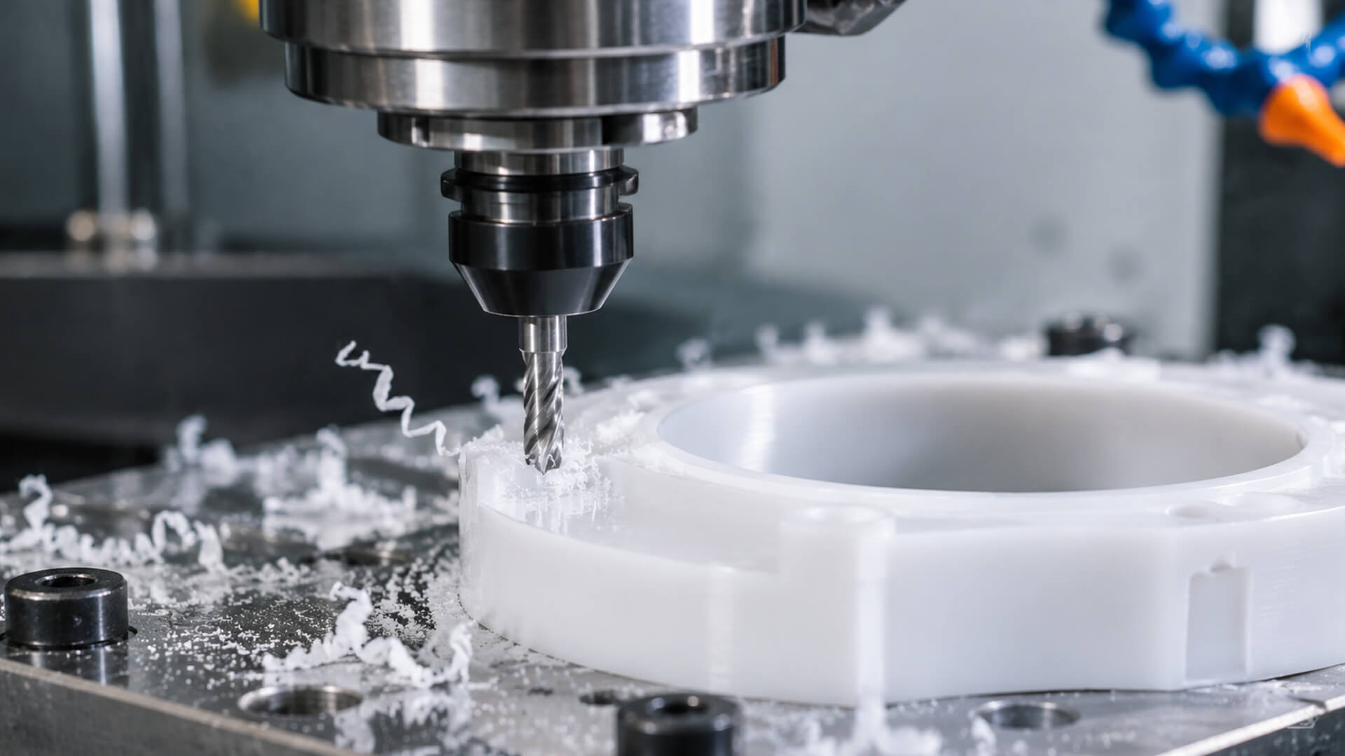
CNC Machining Polycarbonate (PC): Speeds, Tooling, Stress Annealing & Vapor Polishing for Optical Clarity

Polycarbonate (PC)—frequently specified under trade names such as Sabic Lexan or Covestro Makrolon—occupies a unique thermodynamic and mechanical position among engineering thermoplastics. Exhibiting an isotropic light transmittance of 88% to 90%, an index of refraction of 1.586, and an Izod notched impact energy exceeding 600 to 800 J/m (rendering it virtually shatterproof at 250 times the impact resistance of float glass), PC is the structural material of choice for demanding optical, aerospace, and life-science applications.
Engineers rely on precision-machined polycarbonate for diagnostic microfluidic manifolds, avionics HUD combiners, ballistic vision ports, and surgical device housings.
However, achieving optical water-clarity and structural integrity through subtractive manufacturing presents an engineering contradiction. Polycarbonate possesses an extremely low thermal conductivity (k≈0.19 to 0.22 W/m⋅K, roughly 1/1000th that of structural aluminum alloys) coupled with a glass transition temperature (Tg) of approximately 145°C to 150°C and a heat deflection temperature (HDT) under load of just 130°C to 138°C.
Subtractive tool engagement generates intense localized mechanical shear heating. Because this heat cannot diffuse through the plastic matrix, it concentrates instantaneously at the cutting zone.
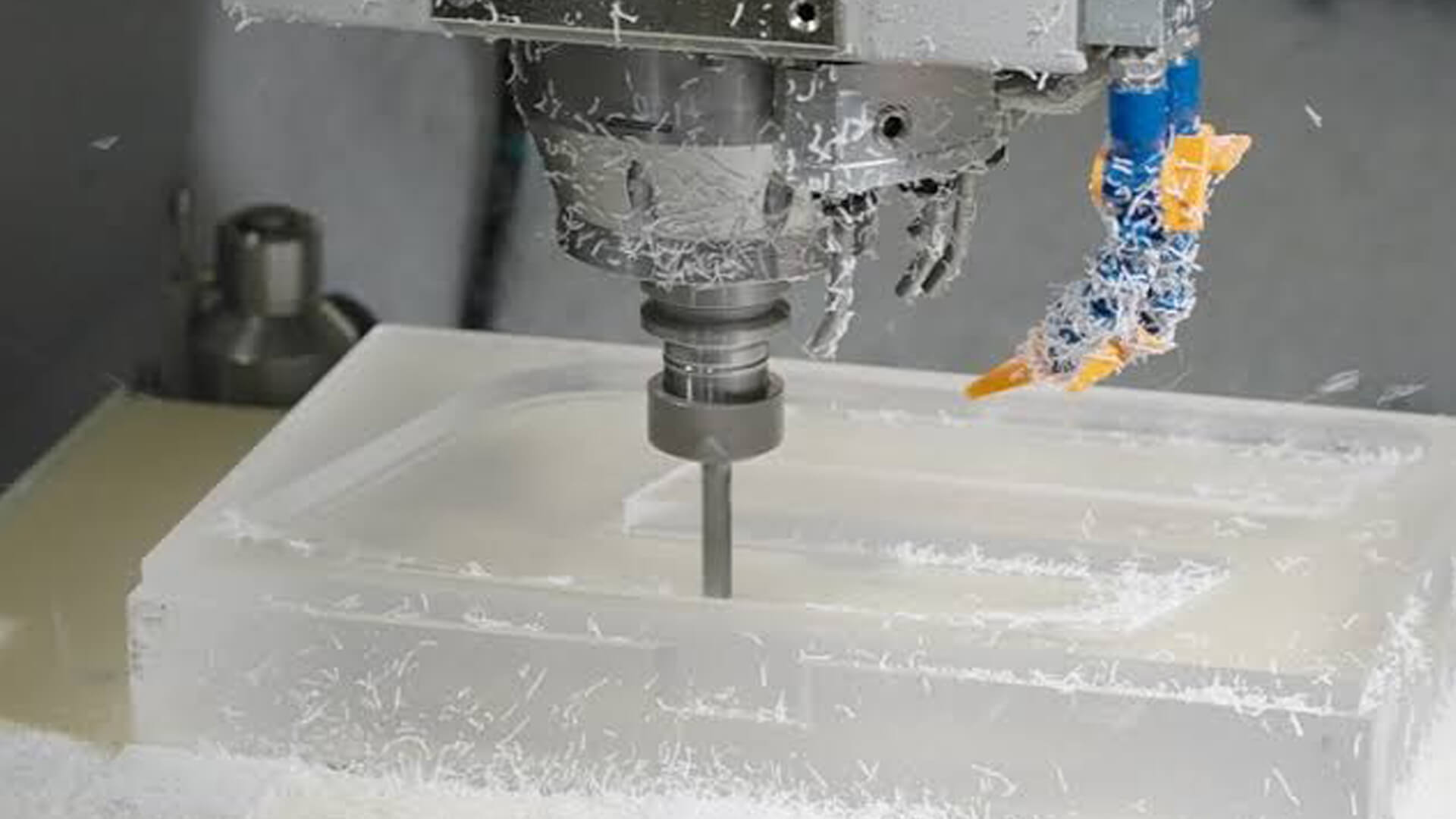
Standard milling cutters induce severe surface gumming, chip re-welding, and microscopic tearing. Even worse, the mechanical shear and localized thermal cycles freeze high residual tensile stresses into the polymer matrix. When cut, the optical surface appears translucent and frosted due to irregular knife-mark diffraction.
If an inexperienced shop attempts to restore clarity via chemical vapor polishing without rigorously controlling residual stress states, the part will suffer catastrophic Environmental Stress Cracking (ESC)—instantly transforming an expensive precision component into an opaque network of spiderweb fractures (crazing).
Successfully converting raw slab stock into an optically transparent, dimensionally stable component held to ±0.005 mm(±0.0002″) requires absolute mastery over cutting mechanics, non-destructive cooling strategies, thermodynamic stress-relief annealing, and controlled chemical vapor reflow.
Below is the engineering protocol applied on the production floor at Celerity Precision for custom polycarbonate CNC machining.
Table of Contents
Surface Finishing Comparison: Mechanical, Thermal, and Chemical Reflow
Raw CNC-machined polycarbonate parts emerge from the milling center with a translucent, matte “frosted glass” appearance (Ra≈0.8 to 3.2μm). This translucency is not a bulk material defect; it is optical diffraction caused by microscopic cusp marks (scallop height) and ductile tool tear lines scattering incoming photons.
Restoring full water-clear transparency requires planarizing these micro-ridges down to a sub-wavelength surface roughness (Ra < 0.05 μm). Four primary finishing methodologies exist, but only one preserves micron-scale internal fluidic geometries.
Finishing Method Comparison Table for Polycarbonate
| Finishing Method | Roughness (Ra µm) |
Clarity (Optical %) |
Internal Channels (Complex 3D) |
Tolerance Impact (Boundary Layer) |
Residual Stress (Induction Risk) |
Typical Applications |
|---|---|---|---|---|---|---|
| As-Machined (Ultra-Fine) Baseline | 0.40 – 0.80 µm | 35% – 50% (Translucent) | Full 3D access via standard tooling | Baseline (±0.005 mm) | High (Shear induced) | Structural housings, internal brackets, hidden fluid channels. |
| Manual Buffing (Diamond/Alumina) Planar Only | 0.05 – 0.10 µm | 80% – 88% | Non-existent (Planar exterior only) | Edge rounding; removes 0.02–0.08 mm | Moderate (Friction heat) | Flat sight glasses, architectural lenses, external cover shields. |
| Direct Flame Polishing Strictly Banned | 0.10 – 0.25 µm | 70% – 82% | Zero (Collapses micro-features) | Severe warping (>0.10 mm) | Extremely High (Craze failure) | Acrylic display only; strictly discouraged for precision PC. |
| Vapor Polishing (DCM Reflow) Optical Gold Standard | <0.02 – 0.05 µm | 88% – 90% (Water-Clear) | Flawless (Cross-drilled 5-axis manifolds) | ≤0.002–0.005 mm controlled layer | Relieved via mandatory annealing | Clinical microfluidic chips, diagnostic manifolds, optical light guides, aerospace vision systems. |
Manual buffing physically strips away dimensional control: buffing wheels wash out crisp mating edges, create non-uniform optical lensing across optical apertures, and cannot access internal passages. Flame polishing—while viable on acrylic (PMMA)—is prone to burning, soot deposition, and thermal degradation on polycarbonate due to its aromatic ring structure and elevated melt viscosity.
Chemical vapor polishing represents the gold standard for clinical and optical instrumentation. By exposing the CNC-machined PC component to a saturated vapor blanket of a volatile solvent (predominantly dichloromethane / DCM), the solvent selectively liquefies an outer surface boundary layer measuring only 2 to 5 microns in depth.
The surface tension of the liquefied polymer matrix pulls the microscopic peaks down into the valleys, self-planarizing the substrate. As the solvent flashes off in an extraction chamber, the surface re-solidifies into an optically flat, amorphous boundary layer possessing identical refractive characteristics to the base stock.
Cutting Mechanics: Eliminating Friction, Smearing, and Micro-Tearing
The low thermal diffusivity of polycarbonate dictates the foundational rule of PC chip formation: the chip must carry away 90% of the generated cutting heat.
When a standard negative- or neutral-rake metalworking tool impacts polycarbonate, it does not shear the plastic cleanly. Instead, it plows through the material, compressing the matrix ahead of the cutting edge.
Because PC has a high elongation at break (100% to 130%), this elastic-plastic compression causes the material to deform beneath the tool edge and drag across the clearance flank. Friction immediately spikes the localized interface temperature above the 135°C HDT threshold. The polymer switches from brittle-ductile shear fracture to viscous, elastic smearing.
Molten swarf sticks to the tool margins, re-welds behind the cut path, and clogs tool flutes within fractions of a second, causing tool snapping and total part gouging.
To prevent smearing:
- Maximize Shear Efficiency: The cutting edge must cut the material under sharp, high-shear positive angles without crushing it.
- Prevent Rubbing Behind the Cut: Generous relief angles are mandatory to prevent the elastic recovery of the polymer from rubbing against the tool clearance face.
- Control Cusp/Scallop Formation: For parts destined for vapor polishing, cutting toolmarks cannot exceed a micro-scallop peak-to-valley threshold of 0.0015 mm(1.5 μm). Vapor polishing cannot melt away deep tool gouges or torn side-wall chatter without melting down adjacent precision features.
Tooling Geometry and Material Physics
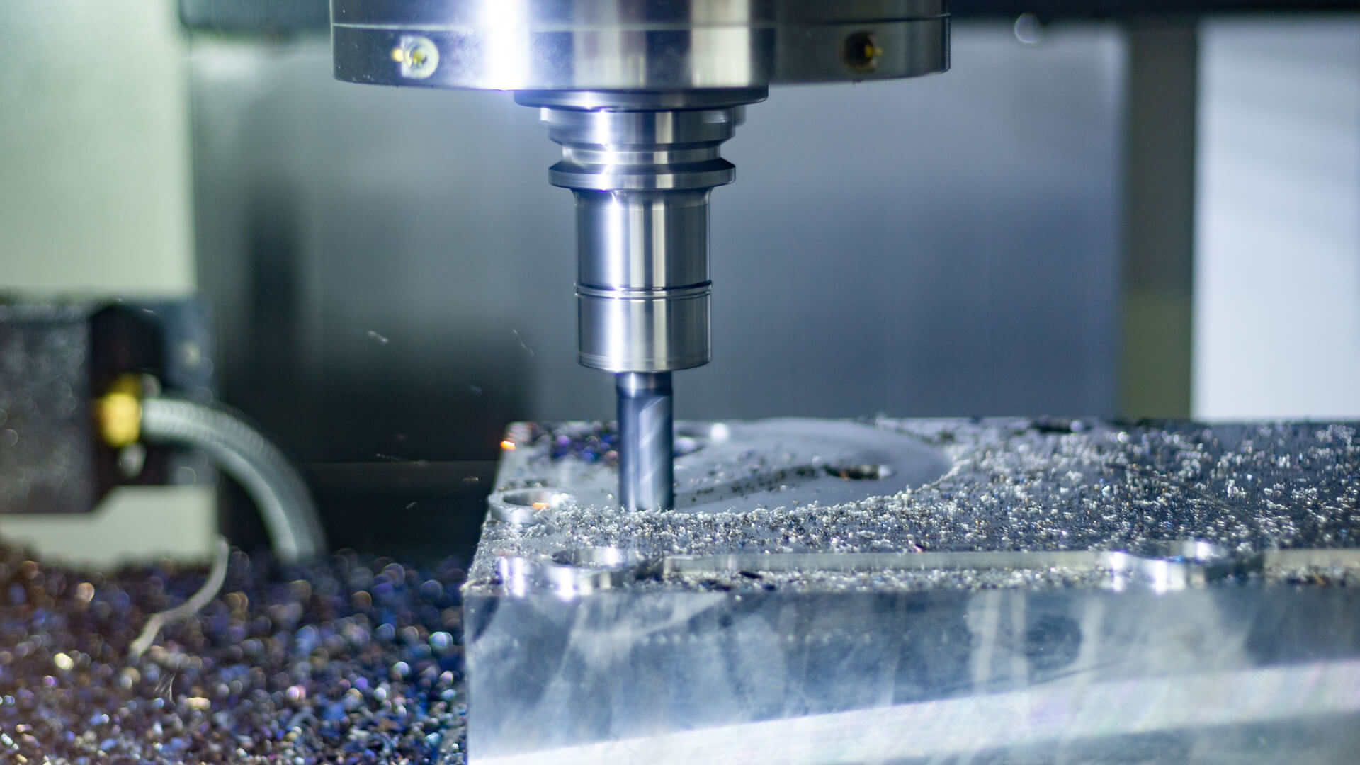
Standard off-the-shelf tungsten carbide end mills designed for steels or general plastics will fail on optical polycarbonate. Successful machining relies on dedicated high-speed aluminum and plastic tooling geometries with mirror-lapped flutes.
| Machining Operation | Tooling Substrate / Coating | Speed (SFM) |
Speed (m/min) |
Chip Load / Feed (FPT / IPR) |
Radial (Ae) | Axial (Ap) |
|---|---|---|---|---|---|---|
| End Milling - Roughing Milling | Polished Solid Carbide (Uncoated) | 500 – 1,000 | 150 – 300 | 0.10 – 0.20 mm/tooth | 0.40 – 0.60 × D | 1.00 – 1.50 × D |
| End Milling - Finishing Milling | Polished Solid Carbide (Uncoated) | 800 – 1,400 | 240 – 425 | 0.03 – 0.08 mm/tooth | 0.05 – 0.15 × D | 0.50 – 1.00 × D |
| Slotting (Full Width) Milling | Polished Solid Carbide (2-Flute) | 400 – 800 | 120 – 240 | 0.06 – 0.12 mm/tooth | 1.00 × D (Full) | 0.50 – 0.75 × D |
| Precision Face Milling Milling | Polished Carbide / PCD Inserts | 800 – 1,500 | 240 – 450 | 0.12 – 0.25 mm/tooth | 0.60 – 0.80 × Cutter D | 1.00 – 2.50 mm |
| CNC Turning - Roughing Turning | Polished Carbide (CCGT) | 600 – 1,200 | 180 – 365 | 0.15 – 0.35 mm/rev | N/A | 1.50 – 4.00 mm |
| CNC Turning - Finishing Turning | Polished Carbide (DCGT) | 800 – 1,600 | 240 – 485 | 0.05 – 0.12 mm/rev | N/A | 0.25 – 0.75 mm |
| Standard Twist Drilling Drilling | Polished High-Helix Carbide | 200 – 400 | 60 – 120 | 0.10 – 0.25 mm/rev | Full Drill D | 1.00 – 2.00 × D (Peck) |
| Deep-Hole Drilling (>3D) Drilling | Parabolic Flute Carbide Drill | 150 – 300 | 45 – 90 | 0.08 – 0.18 mm/rev | Full Drill D | 0.50 – 1.00 × D (Peck) |
Tooling Physics & Long Stringy Chip Management
Standard cutting tools ground for ferrous alloys fail in Delrin production. Steel-cutting end mills feature micro-honed edge radii (15 to 25μm) and neutral or negative rake angles designed to withstand heavy shear forces. In POM, these dull cutting edges plow and compress the polymer, generating friction, expanding the cut face, and creating heavy, stringy burrs along every tool exit plane.
Single-Flute O-Cutter Micro-Geometry Specification
Optical Plastics Tooling Spec- Cutter Core Architecture (Single-Flute “O-Flute” vs. Two-Flute): For pocketing, 2D contouring, and slotting, single-flute solid-carbide “O-flute” cutters provide an expansive, uninhibited chip pocket. This geometry sweeps the high-volume ribbon-like plastic chips away from the shear zone before heat can transfer to the core. For fine multi-axis surface finishing on 3D contoured optical domes, double-flute spherical ball nose tools are utilized, provided they have polished chip breakers.
- Axial and Radial Rake Angles: High positive rake angles ranging from +15° to +20° slice cleanly through the long-chain bisphenol-A polymer backbones, minimizing mechanical strain.
- Primary and Secondary Relief: Primary clearance relief angles must be ground to 12° to 15°, backed by a secondary clearance of 20°. This prevents the cut polycarbonate from flexing elastically against the non-cutting zones of the carbide tool body.
- Substrate & Coating Topography: Use un-coated micro-grain carbide (0.5 μm grain size). Physical Vapor Deposition (PVD) coatings (such as AlTiN or TiCN) naturally round the cutting edge radius over 5 to10 μm, promoting elastic deflection and melting. The cutting edge must remain razor-honed (rϵ< 2 μm). Flutes must be micro-polished using diamond compounds to a mirror finish (Ra< 0.05 μm) to eliminate chip-flute friction. Single-crystal natural diamond (MCD) or polycrystalline diamond (PCD) inserts are deployed on fly-cutters for non-ferrous face milling to produce near-mirror pre-polishing baselines.
Speeds, Feeds, and Machining Protocols
Polycarbonate machining demands higher surface speeds paired with deliberate, rigid chiploads. Feed-per-tooth must never drop below a threshold where the cutting edge rubs rather than cuts.
Clear unfilled polycarbonate behaves in a ductile manner, requiring chip-evacuation clearance.
In contrast, 20% to 30% glass-filled PC (e.g., Lexan 3412R) contains highly abrasive chopped borosilicate glass fibers; it machines with high chip abrasiveness and shear brittleness, requiring reduced cutting speeds and wear-resistant tool coatings.
Comprehensive Machining Parameters: Unfilled Clear PC vs. Glass-Filled PC
| Operation & Material | Tool Configuration | Speed (SFM) |
Speed (m/min) |
Chip Load / Feed (FPT / IPR) |
Stepover (ae) |
Depth (ap) |
Toolpath & Cooling Strategy |
|---|---|---|---|---|---|---|---|
| End Milling (Rough) Clear PC | 1-Flute / 2-Flute Polished Carbide | 800 – 1,500 | 245 – 460 | 0.08 – 0.15 mm/z | 40% – 60% Dc | 1.0 × Dc max | Climb milling; High-flow Cold Air Gun (-10°C) or Pure DI Water flood. |
| End Milling (Rough) 20-30% GF | 2-Flute / 3-Flute Diamond (DLC/PCD) | 400 – 700 | 120 – 215 | 0.05 – 0.10 mm/z | 30% – 50% Dc | 0.75 × Dc max | Climb milling; Extreme vacuum dust extraction or filtered water flood. |
| End Milling (Finish) Optical Path | 2-Flute Mirror-Polished O-Flute | 1,200 – 2,200 | 365 – 670 | 0.03 – 0.06 mm/z | 0.03 – 0.05 mm | 0.10 – 0.25 mm | Constant scallop control; Spindle 18,000 – 24,000 RPM; Continuous air blast. |
| End Milling (Finish) 20-30% GF | 2-Flute Ultra-Fine Grain DLC Carbide | 500 – 900 | 150 – 275 | 0.02 – 0.05 mm/z | 0.05 – 0.08 mm | 0.15 – 0.30 mm | Climb milling only; Avoid dwelling to prevent perimeter glass-matrix tearout. |
| Precision Turning (Rough) Clear PC | Ground High-Positive Carbide (PCD Tip) | 600 – 1,000 | 180 – 305 | 0.15 – 0.25 mm/rev | N/A | 1.0 – 2.5 mm | Continuous chip flow; maintain dynamic chip breaker; Cold air blast. |
| Precision Turning (Finish) MCD Optical | MCD / Polished Diamond (rε = 0.2 mm) | 1,000 – 1,600 | 305 – 490 | 0.02 – 0.06 mm/rev | N/A | 0.05 – 0.15 mm | Direct optical path baseline; strictly ban stops/pauses during feed. |
| Deep-Hole Drilling Clear PC | Parabolic Twist Drill (118° → 90° mod) | 200 – 450 | 60 – 140 | 0.05 – 0.12 mm/rev | Full Drill Diameter | 0.5 – 1.0 × D (Peck) | Modify point angle to 90°; modify rake to neutral; peck to extract heat. |
| Micro-Drilling (≤1.0mm) Clear PC | Dedicated Micro-Solid Carbide Drill | 150 – 300 | 45 – 90 | 0.005 – 0.015 mm/rev | Full Drill Diameter | 0.1 – 0.2 × D (Peck) | High-pressure deionized micro-mist; continuous high-frequency peck cycles. |
Critical CAM Programming Strategies:
- Climb Milling Exclusively: Never use conventional (up) milling. Conventional toolpaths cause the cutter tooth to rub along the finished surface before engagement, work-hardening and heating the PC, which forms a smeared, micro-fractured perimeter.
- Ramping and Helical Entry: Plunge cuts along the Z-axis are prohibited. The tool tip has near-zero surface speed at the center, packing chips against the floor. Program helical entries at angles between 2° and 3° to keep swarf ejecting upwards.
- Scallop / Cusp Height Calculation: In 3D contour ball-milling (such as machining parabolic lenses or hemispherical dome covers), stepover (ae) directly dictates maximum cusp height (h). Using a ball mill of radius R:
h ≈ aₑ² / (8R)
To prepare a 3D surface for chemical vapor polishing, programming must hold h≤0.001 mm(1.0 μm). For a 6.0 mm ball mill (R=3.0 mm), maximum allowable stepover must not exceed:
aₑ = √(8 × 3.0 × 0.001) ≈ 0.155 mm
For pure optical transparency, Celerity engineers program finishing passes using a stepover of 0.03 to 0.05 mm.
Coolant Protocols: The Absolute Ban on Oil-Based Fluids
The chemical vulnerability of polycarbonate centers around Environmental Stress Cracking (ESC). Polycarbonate’s bisphenol-A aromatic carbonate structure is sensitive to hydrocarbons, esters, ketones, halogenated additives, and cyclic amines.
ABSOLUTE BAN ON MINERAL OIL AND SYNTHETIC WATER-SOLUBLE EMULSIONS
Standard metalworking coolants (soluble cutting oils, semi-synthetics, and extreme-pressure sulfurized/chlorinated fluids) chemically attack the amorphous polymer chains of Polycarbonate, inducing catastrophic solvent crazing.
This micro-void damage may occur immediately upon tool contact or remain entirely latent — escaping in-process visual QA and manifesting weeks later in the field as spontaneous structural shattering and permanent optical clouding under routine operational loads.
When polycarbonate experiences localized tensile stresses (inherent to mechanical chip formation), aromatic hydrocarbon molecules from oils or emulsifiers penetrate the intermolecular polymer chain spaces.
This chemically plasticizes the polymer chains, dramatically lowering the energy needed to open craze cracks.
Within minutes, micro-fissures propagate throughout the part, turning it structurally weak and milky white.
Permitted Cooling Configurations on Celerity Shop Floor:
- Compressed Vortex Cold-Air Guns (Primary Choice): Utilizing Ranque-Hilsch vortex cooling tubes delivering compressed air at −10°C to −5°C directly targeted at the tool edge. This blast strips chips away from the tool and rapidly cools the cut zone without chemical exposure.
- Pure Deionized (DI) Water Flood: For high-speed micro-milling manifolds where dry chips could scratch the surface, pure filtered deionized water without surfactants or rust inhibitors serves as an inert, high-heat-capacity coolant.
- MQL Using Pure Isopropanol / High-Purity Ethanol: Under controlled ventilation, minimum quantity lubrication (MQL) with high-purity alcohols can be deployed for precision facing cuts. The alcohol flashes off rapidly, providing evaporative cooling without inducing stress cracks.
Chemical Vapor Polishing (Dichloromethane / DCM) Mechanics
Chemical vapor polishing is an engineering art governed by thermodynamic equilibria, diffusion coefficients, and precise atmospheric exposure cycles.
Chemical Vapor Polishing (DCM Reflow) Process Architecture
Optical Micro-Reflow PhysicsThe Reflow Mechanism:
- Phase Change & Vapor Generation: A dedicated vapor generation unit heats industrial-grade dichloromethane (Methylene Chloride, CH₂Cl₂, boiling point 39.6°C) or proprietary fluorocarbon blends (such as Weld-On 4 formulations) within an enclosed processing chamber. Because DCM vapor is three times denser than air, it forms a controllable vapor blanket.
- Selective Condensation: The machined PC component—pre-conditioned to a uniform stabilization temperature (50°C to 60°C)—is exposed to the vapor envelope. As the solvent vapor hits the polycarbonate surface, it condenses into a microscopic liquid film.
- Surface Reflow: Polycarbonate dissolves in DCM. The liquid film disrupts secondary intermolecular hydrogen bonding and van der Waals bonds within an exterior depth of 2 to 5 μm, forming a short-lived liquid solution layer. Surface tension acts immediately: the meniscus of the liquefied polymer smooths away micro-peaks and fills tool troughs.
- Flash Desorption: The part is extracted into an ultra-clean, heated evacuation zone (70°C to 80°C). The low-boiling solvent evaporates rapidly. The polymer chains snap back into an amorphous, glass-like molecular packing state, achieving optical clarity (Ra< 0.02 μm) without dimensional deformation.
Polishing Intricate Internal Geometries:
Mechanical buffs cannot reach inside complex internal structures, such as a 5-axis cross-drilled clinical manifold with intersection angles. Vapor polishing handles these features effectively:
- The gaseous solvent penetrates micro-fluidic channels down to 0.20 mm (200 μm) inner diameter.
- Capillary action draws the vapor along interior walls, smoothing out internal drilling peck-rings and reamer chatter marks.
- Light passing through the manifold encounters planarized internal walls, eliminating scatter and enabling unhindered spectroscopic and optical diagnostic sensing.
The Mandatory Pre- and Post-Machining Annealing Cycle
Attempting to vapor-polish an as-machined polycarbonate part without thermal annealing leads to immediate scrap.
The cutting tool leaves behind tensile and compressive stress gradients locked within the polymer chains. When the solvent vapor breaks open these surface bonds, the internal stress forces balance out instantly, releasing through microscopic fissures (crazing) across the entire component.
Polycarbonate (PC) Stress-Relief Annealing Profile
Optical Integrity ProtocolThermal Annealing Protocol: Optical-Grade Virgin PC
Standard Operating ProcedureWhy Thermal Control is Vital:
- The Glass Transition Threshold: Annealing takes place just below polycarbonate’s glass transition temperature (Tg≈145°C). At 122°C, the molecular chains gain enough thermal mobility to relax without causing the part to deform under gravity.
- Preventing Secondary Thermal Stress: Exceeding a cool-down rate of 10°C/hr will re-introduce thermal stress. The exterior skin cools, contracts, and hardens while the core remains warm and expanded. The resulting volumetric shrinkage will trap new tensile stresses in the outer layer, leading to crazing during vapor polishing.
- Two-Step Annealing for Complex Optics: For ultra-precision optical parts, run an initial rough-machining cycle leaving +0.5 mm stock, perform rough-annealing, execute high-speed finish passes to final net shape, run an intermediate finish-anneal, and then introduce the part to the vapor-polishing chamber.
Precision Manufacturing on Celerity Shop-Floor Equipment
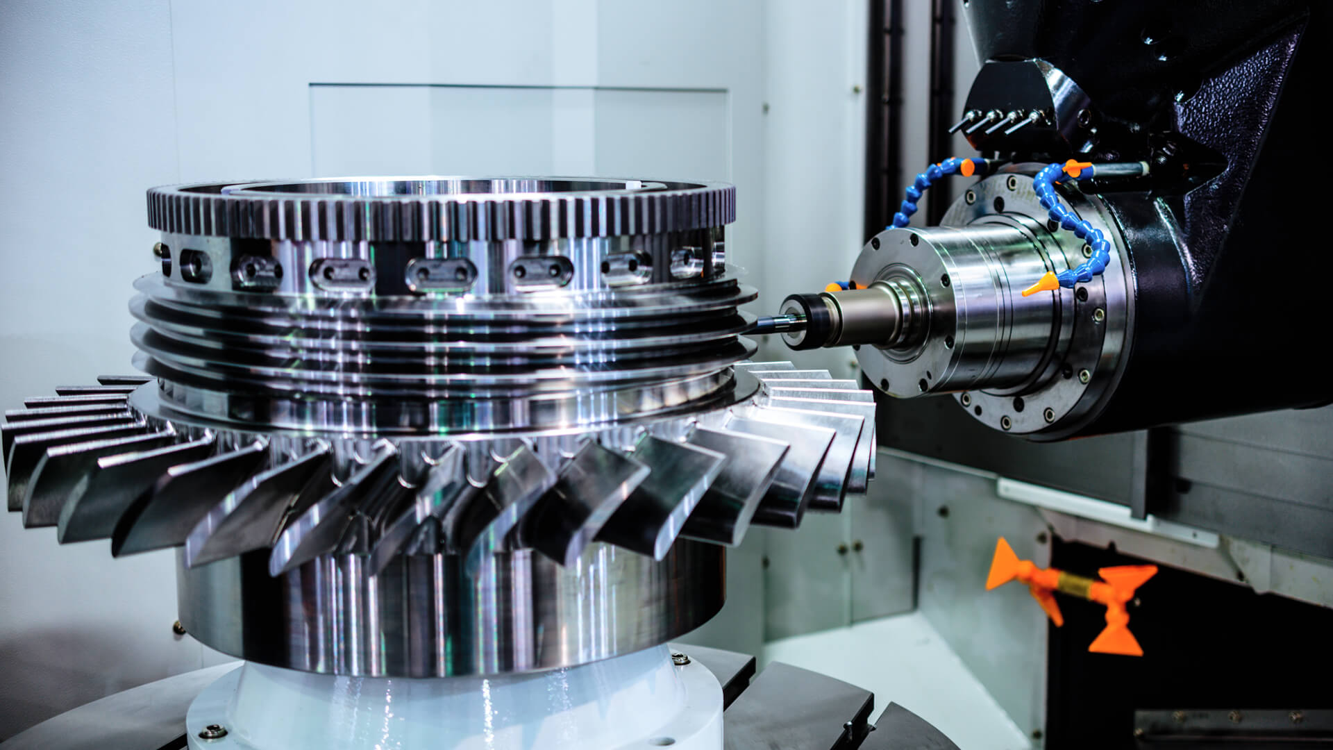
Translating these processing rules into sub-micron parts requires rigid, high-performance machine tools and multi-axis kinematics, as detailed in our precision CNC milling capabilities.
Celerity Production & Metrology Infrastructure
E-E-A-T Facility FootprintBeijing Jingdiao (JDGR200T) 5-Axis
- 24,000 RPM Spindle: High-frequency electro-spindle eliminates plastic melting and burrs.
- Micro-Tooling Down to Ø0.10 mm: Slices microfluidic channels and sensor cavities without tool deflection.
- Optical Finish: Delivers mirror-like finishes (Ra ≤ 0.2 µm) straight off the machine.
German Hermle C400 5-Axis Center
- Single-Setup Multi-Face Machining: Full 5-sided geometric control eliminates re-clamping datum stack-up.
- Mineral-Cast Damping Bed: Absorbs micro-harmonics, protecting diamond and carbide edges.
- Zero Clamp Distortion: Eliminates localized clamp marks on soft, high-value optical polymers.
Climate-Controlled QA Lab (20°C ± 0.5°C)
- Non-Contact VMM Optical Testing: Automated image inspection captures flexible seals and lips with zero contact force.
- Zeiss CMM Ultra-Low Force Probing: Trigger force < 0.03N prevents stylus indentation on soft plastics.
- Verified Aerospace Tolerances: Multi-axis spatial GD&T certified down to ±0.005mm (±0.0002").
- Micro-Channel Milling (Beijing Jingdiao JDGR200T): Equipped with a 4,000 RPM high-frequency direct-drive electro-spindle, fully active thermal displacement compensation, and glass scales with 0.1 μm resolution, this platform delivers the continuous feed speeds needed to prevent thermal melting in micro-features. Micro-endmills down to ∅0.10 mm execute complex diagnostic lab-on-a-chip channels without tool chatter or burrs.
- Multi-Sided Optical Prisms (German Hermle C400 5-Axis): Re-clamping a pristine polycarbonate lens in a secondary vise will crush the material, dent the plastic, and leave clamp-induced optical birefringence. The rigid trunnion table of the Hermle C400 allows multi-sided access to optical faces, prisms, and cross-ports in a single setup, locking in true geometric runouts under ±0.005 mm.
Quality Verification for Precision Optical Components
Because polycarbonate scratches easily (pencil hardness B to HB) and optical lenses rely on sub-micron profiles, quality inspection cannot rely on heavy-duty touch probes.
Measures radii, channel depths, and hole locations non-destructively
- Non-Contact Vision Metrology (Automatic Image Measuring Instrument / VMM): Parts are transferred into our temperature-controlled metrology laboratory (20°C ± 0.5°C). The VMM utilizes programmable transmitted and coaxial multi-angle LED ring lighting paired with high-resolution telecentric lenses. Sub-pixel edge algorithms verify internal flow-path widths, fluidic junction blend radii, and true positions without touching the vapor-polished face.
- Low-Force Contact Metrology (Zeiss CMM): When complex external 3D profiles require coordinate validation, our Zeiss CMM uses ultra-low force continuous scanning probe heads (FN<0.05 N). Silicon nitride or ruby styli move along the surface without scuffing the soft polymer or causing local deflection.
- Raw Stock Authentication (XRF & Spectrophotometry): Virgin medical stock must not contain recycled regrind or styrene blends. Incoming sheet and rod stock (Sabic Lexan 101R / 9034 / Makrolon 2807) are evaluated using on-site X-Ray Fluorescence (XRF) spectrometry to verify the absence of heavy metal stabilizers, accompanied by optical refractometers measuring raw lot refractive indices (nD=1.586 ± 0.002).
DFM Rules for Optical Polycarbonate Components
Applying clean Design for Manufacturability (DFM) principles early helps avoid high scrap rates and keeps custom parts running smoothly through machining and polishing.
Design for Manufacturability (DFM)
Internal Radii Transitions
R ≥ 0.5 mm (0.020") | Preferred R ≥ 1.0 mm
Polycarbonate has high notch sensitivity. Sharp 90° internal corners act as localized stress concentration risers, triggering spontaneous crazing and micro-fractures during vapor exposure.
Eliminate Blind Micro-Holes
Depth-to-Diameter > 3:1
Heavy solvent vapor condenses and pools at the bottom of deep blind holes with no escape path. Trapped liquid chemically dissolves and melts cavity bottoms into opaque gel pockets. Use through-holes.
Uniform Cross-Sections
≤ 1.5:1
Abrupt wall thickness variations cause uneven heat transfer during the 120°C stress-relief anneal. Differential core-to-skin contraction traps residual tensile stresses that produce optical wave lensing.
Vapor Drainage & Venting Paths
Entry/Exit Venting Ports for cavities
Enclosed microfluidic channels require uninterrupted vapor circulation and vacuum evacuation. Dedicated flow paths ensure instant solvent flash-off, eliminating droplet marks on optical faces.
1. Internal Fillet Radii (R ≥ 0.5 mm):
Polycarbonate has a notch sensitivity factor ( q ≈ 0.25 to 0.35). Sharp internal 90° square corners act as stress concentration risers.
During thermal cycling and vapor polishing, cracks naturally initiate at sharp internal corners. Fillet all internal pockets to at least R ≥ 0.5 mm(R ≥ 1.0 mm preferred), allowing CNC endmills to clear the path smoothly while maintaining continuous chip load.
Internal Corner Radius vs. Stress Concentration
Sharp Internal Corner
- Notch Sensitivity: Polycarbonate is highly sensitive to sharp notches. Sharp transitions multiply cutting forces into extreme localized tensile strain.
- Solvent Crazing: During chemical vapor polishing (DCM), solvent rapidly attacks the high-strain corner, initiating spiderweb craze fractures.
Uniform Blended Radius
- Smooth Toolpaths: Allows CNC endmills (Ø1.0mm+) to maintain continuous tangential motion without deceleration or tool chatter.
- Craze Elimination: Disperses localized thermal-mechanical shear stress, allowing safe DCM vapor flow and zero post-polish cracking.
2. Avoid Deep Blind Holes (L / D > 3 : 1):
When vapor polishing, volatile solvent enters every recess. In a deep blind hole, heavy solvent vapor condenses and pools at the bottom.
Without an exit path, the pooled liquid solvent attacks the base of the hole, melting away dimensions and turning the bottom cloudy.
Where possible, convert blind holes into through-features, or reduce hole depth ratios below 2.5:1.
3. Maintain Balanced Wall Sections:
Abrupt wall thickness variations (e.g., transitions from an 8.0 mm structural flange to a 0.8 mm fluidic membrane) cause internal thermal gradients during stress annealing.
The thin zone cools rapidly while the thick zone continues to contract, freezing high internal stresses along the transition boundary. Maintain wall thickness balance within a 1.5:1 envelope across the component.
4. Provide Polishing Drainage and Vent Ports:
For closed-loop microfluidic chips and manifolds, design passive bypass channels or temporary sub-ports into the fixture locations.
This ensures polishing vapor sweeps continuously across internal channels and evacuates cleanly under dry vacuum, preventing puddling along fluid path floors.
Precision Optical Polycarbonate Manufacturing at Celerity
At Celerity Precision, we machine high-tolerance engineering polymers across our multi-axis centers. For broader plastic capabilities, review our custom plastic CNC machining services.
Whether you are scaling production on microfluidic clinical manifolds, light guides, or impact-resistant aerospace vision systems, our team provides full lifecycle support—from DFM design reviews and high-speed CNC milling to controlled thermal annealing and water-clear vapor polishing.
Start Your Next Optical PC Project
Submit your 3D CAD files (STEP, IGES, or native solid models) to our application engineering team. We deliver complete, actionable DFM manufacturability evaluations alongside guaranteed quote packages within 24 hours.

CP Engineering Team
Authored and peer-reviewed by the Senior Engineering and Metrology Team at Celerity Precision. Backed by German 5-axis CNC machining centers, high-speed micro-milling platforms, and a climate-controlled Zeiss CMM inspection lab, our team delivers deep DFM insights, material machinability guides, and precision manufacturing solutions for aerospace, medical, and semiconductor developers worldwide.